background image

AEZZP0CB - MDI-CAN - User Manual 

Page - 3/13 

Contents 

1


FEATURES............................................................................................................................4


1.1


Specifications..............................................................................................................4


1.2


Functional descriptions ...............................................................................................5


1.2.1


LED function .................................................................................................5


1.2.2


Display function.............................................................................................5


2


INSTALLATION.....................................................................................................................7


2.1


Connection scheme ....................................................................................................7


2.2


Dimensions .................................................................................................................8


2.3


Connector description.................................................................................................9


3


HOUR-METER MEMORY SERVICE...................................................................................10


4


ALARMS..............................................................................................................................11


4.1


Decoding of the alarms displayed on the MDI-CAN .................................................11


APPROVAL SIGNS 


COMPANY FUNCTION 

INIZIALS

SIGN 

GRAPHIC AND LAYOUT 

FF 


PROJECT MANAGER 

FG 


TECHNICAL ELECTRONIC 

MANAGER VISA 

PP  

SALES MANAGER VISA 

PN 


Publication N°: 

AEZZP0CB


Edition: 

July 2007 


U


This manual describes the new MDI-CAN with the Can bus termination 
resistance wich can be connected through an external jumper applied 
between CNA-5 and CNA-6. See also chapter 2.3 for the pin description. 

Summary of Contents for MDI-CAN

Page 1: ...LECTRONIC OLEODYNAMIC INDUSTRIAL EQUIPMENTS CONSTRUCTION Via Parma 59 42028 POVIGLIO RE ITALY Tel 39 0522 960050 r a Fax 39 0522 960259 e mail zapi zapispa it web www zapispa it EN User Manual MDI CAN...

Page 2: ...anges or improvements to its products at any time and without notice The present publication reflects the characteristics of the product described at the moment of distribution The publication therefo...

Page 3: ...VICE 10 4 ALARMS 11 4 1 Decoding of the alarms displayed on the MDI CAN 11 APPROVAL SIGNS COMPANY FUNCTION INIZIALS SIGN GRAPHIC AND LAYOUT FF PROJECT MANAGER FG TECHNICAL ELECTRONIC MANAGER VISA PP S...

Page 4: ...roprocessor This algorithm considers the condition of braking or large acceleration current demands from the drive motor Using the Zapi PROGRAMMING CONSOLE it is possible to make a selection from 100...

Page 5: ...XXX represents the version MDI CAN and then traction controller Eprom Version appears each one for 2 seconds Simultaneously the symbol of a Monkey Wrench appears Battery State of charge The battery s...

Page 6: ...st solution to the problem Hourglass Symbol It is normally off it blinks when the Hour Meter is working 4 When the Key Switch is closed the MDI CAN makes a general test lighting all the display liquid...

Page 7: ...AEZZP0CB MDI CAN User Manual Page 7 13 2 INSTALLATION 2 1 Connection scheme HOURMETER MAINTENANCE ALARMS SPEED REDUCTION ALARMS HOURS BATTERY CHARGE...

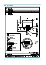
Page 8: ...Page 8 13 AEZZP0CB MDI CAN User Manual 2 2 Dimensions HOURMETER MAINTENACE PLAN SPEED REDUCTION ALARMS BATTERY CHARGE...

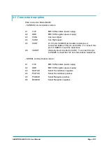
Page 9: ...on resistance is connected between this pin and CANL To connect this pin to CNA 6 to insert the resistance A6 CANHT Internally short circuited to CANH To connect this pin to CNA 5 to insert the 120 oh...

Page 10: ...NCTION1 Open and close the key Switch The replacement controller will now receive and retain the machine hour meter value of the previous controller It has to be considered that On default the paramet...

Page 11: ...MDI CAN and after reference to the following table the operator can solve the problem if the failure is not serious It will also be necessary to refer to the paragraph describeg the Alarms in the Man...

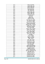
Page 12: ...40 BRAKE CONT OPEN A41 DIR CONT CLOSED A42 DIR CONT OPEN A43 RIGHT CONT CLOSED A44 RIGHT CONT OPEN A45 LEFT CONT CLOSED A46 LEFT CONT OPEN A47 MAIN CONT CLOSED A48 MAIN CONT OPEN A49 I 0 EVER A50 LEFT...

Page 13: ...A90 DRIVER 1 KO A91 DRIVER 2 KO A92 DRIVER 1 SIC KO A93 DRIVER 2 SIC KO A94 INPUT ERROR 6 A95 INPUT ERROR 5 A96 INVERSION A97 POSITION HANDLE A98 INPUT ERROR 2 A99 INPUT ERROR 1 4 The 16A06 string cor...

Reviews: