background image

Page 22

6)

AUX FUNCTION #1

On

the Combi hour-meter is immediately over-written by that of MDI
instrument.

Off

In this configuration the alarm "AL98" will be displayed on the MDI
for 1 minute. If during this minute the user doesn't set ON the "Aux
function #1", the MDI hour-meter will be over-written by that of the
controller.

7)

CHECK UP ENABLE

On

This function sets an alarm (AL99, Check Up Needed) after 300
hours which informs the operator that it is necessary to make
assistance service on the machine.

Off

This function is disabled.

8)

CHECK UP DONE

On

This option enables to reset the check-up hour-meter and the alarm
"Check Up Needed".

Off

This function is disabled.

Summary of Contents for COMBI SEM-1

Page 1: ...Connection 10 3 1 Combi Sem 1 connection drawing 10 3 2 Serial tiller connection drawing 11 3 3 Description of combi sem 1 connectors 12 3 3 1 Connector A description 12 3 3 2 Connector B description 12 3 3 3 Connector C description 13 3 3 4 Connector D description 14 3 3 5 Connector E description 14 3 3 6 Connector F description 16 3 4 Combi Sem 1 power connection 16 4 Regulation 17 4 1 Zapi Prog...

Page 2: ...y this symbol are essential for the safety SIGNATURES TABLE S E C I V R E S T P E D Y N A P M O C E V I T U C E X E T N E M E G A N A M E V I T U C E X E N O I T C E S G N I R E E N I G N E R E G A N A M T R O P X E Publications N AD3ZP0AA Edition September 2000 ...

Page 3: ...ontroller for series excited motors Drivers for ON OFF electrovalves and for one proportional valve electrodistributor Interface for serial tiller head MDI interface Multifunction Digital Instrument battery discharge indicator hourmeter alarms programmed maintenance 1 3 MAIN FEATURES High frequency MOSFET controller high efficency silent etc Speed control with regenerative braking controls the tru...

Page 4: ...ion against accidental Start Up A precise sequence of operations is necessary before the machine starts If these operations are not carried out correctly the machine stops Driving requests must be made after closing the Key Switch Protection against uncontrolled movements The Main Contactor will not close if The Power Unit is not operating correctly The Logic Unit is not operating correctly The Se...

Page 5: ...Drivers Current Sensors 3 Driving diagnosis that checks Watchdog VMN Point Current Contactor s 4 Continuos Diagnosis that checks Chopper temperature Battery Voltage 1 7 MAIN CONTACTOR AND SAFETY BUTTON Battery disconnection should be made according to the Diagram below In order to avoid damage to the controller during the regenerative phase the supply to the Key Switch must be cut off at the same ...

Page 6: ...ed to a traction battery Do not use converters outputs or power supplies For special applications please contact the nearest Zapi Service Centre In the first instance start the machine with the drive wheels raised from the floor to ensure that any installation error do not compromise safety After operation even with the Key Switch open the internal capacitors may remain charged for some time For s...

Page 7: ...s has been carried out correctly 2 1 CONNECTION CABLES For the auxiliary circuits use cables bigger or equal to 0 5mm2 section For power connections to the motor pump and traction rotor and to the battery use cables of 16 25 mm2 section The cables from chopper to battery should be run side by side and be as short as possible 2 2 CONTACTORS A Main Contactor designed for Continuous Operation should ...

Page 8: ...Page 8 2 4 COMBI SEM 1 CONTROLLER MECHANICAL DRAWING ...

Page 9: ...Page 9 2 5 SERIAL TILLER MECHANICAL DRAWING ...

Page 10: ...Page 10 3 CONNECTION 3 1 COMBI SEM 1 CONNECTION DRAWING ...

Page 11: ...Page 11 3 2 SERIAL TILLER CONNECTION DRAWING The folllowing drawing is an example of typical tiller head functions ...

Page 12: ...lectrovalves coils B1 BATT Positive after the main contactor is the electrovalves positive B2 NMC Negative of the main contactor B3 BATT Negative free for the customer B4 BATT Negative free for the customer B5 NEB Negative of the electromechanical brake B6 NEVP Negative of the proportional electrovalve B7 NEV2 NHO Negative of the electrovalve 2 option negative of the horn B8 NEV1 Negative of the e...

Page 13: ...closed The positive for the brake and all the other ON OFF valves comes from the main contactor so these loads do not affect the key input but only the auxiliary fuse 3 3 3 Connector C description The C connector manages the serial link of the tiller card C1 BATT Negative free for the customer C2 BELLY Quick inversion microswitch input This signal is directly connected with the Combi for safety re...

Page 14: ...the console or the MDI instrument D9 NCLRXD Negative of the reception from the console or the MDI instrument D10 NOT USED Free Note The console must be connected to D at the place of MDI by means of an adaptor follow the table for the right connections 3 3 5 Connector E description The E connector manages the inputs from the chassis of the truck E1 INPUT 1 This is a digital input free for customer...

Page 15: ... reason E12 BATT Negative free for the customer E13 INPUT 2 This is a digital input free for customer request The meaning depends on the software installed made by Zapi and the model selected with the input E9 and E10 E14 CM Positive for the Input 3 is a key switch signal interrupted by a diode for safety reason E15 BATT Negative free for the customer E16 CM Positive for the Input 4 is a key switc...

Page 16: ...to the pin2 of the A connector is a backing signal 3 4 COMBI SEM 1 POWER CONNECTION BATT before FUSE Positive of the battery after the main contactor BATT after FUSE Positive of the battery after the main cont and after the fuse BATT Negative of the battery F1 F2 Field connections for traction motor VMNT Traction motor current sensor input VMNP Pump motor input without the current sensor ...

Page 17: ...the parameter of the Combi 1 Roll Up push to scroll up the submenu and to select a parameter 2 Roll Down push to scroll down the submenu and to select a parameter 3 Enter push to have access to the selected submenu or to confirm a changement 4 Out push to exit the selected menu or to refuse a changement 5 Set Up push to increase a parameter 6 Set Down push to decrease a parameter Note After a modi...

Page 18: ...Page 18 4 2 DESCRIPTION OF STANDARD CONSOLE MENU ...

Page 19: ...tained by weakening the field current after reaching 100 conduction on the armature With the parameter set at level 0 the armature is in full conduction but the field current does not decrease below the nominal value low speed 10 TRACTION I MAX t Sets the maximum current of the Chopper Armature 11 ARMA NOM CURR t Nominal armature current This parameter fixes a limit for the armature current above ...

Page 20: ...d 23 R SHIFT SPEED p Right shift maximum speed 24 L SHIFT SPEED p Left shift maximum speed 25 MIN EVP COARSE p Sets the minimum voltage applied to the EVP This is a big regulation 26 MAX EVP COARSE p Sets the maximum voltage applied to the EVP This is a big regulation 27 MIN EVP FINE p Sets the minimum voltage applied to the EVP This is a fine regulation 28 MAX EVP FINE p Sets the maximum voltage ...

Page 21: ...K On the battery discarge level check is carried on when the battery level reaches 10 an alarm is signaled and the maximum current is reduced to the half of the programmed value Off the battery discarge level check is carried on but no alarm is signaled 3 AUX FUNCTION 2 Present Proportional electrovalve present Absent Proportional electrovalve not present Will be driven like an On Off electrovalve...

Page 22: ...et ON the Aux function 1 the MDI hour meter will be over written by that of the controller 7 CHECK UP ENABLE On This function sets an alarm AL99 Check Up Needed after 300 hours which informs the operator that it is necessary to make assistance service on the machine Off This function is disabled 8 CHECK UP DONE On This option enables to reset the check up hour meter and the alarm Check Up Needed O...

Page 23: ...HARGE 60 This check is made during the initial diagnosis This Alarm is generated if the capacitors are not charged within 500 mSec after the Key switch on Probable cause is a failure within the power block 5 VMN NOT OK 32 This test is performed at rest with the Main Contactor closed and also during operation This Alarm is generated if the VMN is lower than battery voltage in stand by This alarm is...

Page 24: ...efective d the values set during the acquisition procedure are wrong 9 I 0 EVER 49 This check is made while driving If the current is not higher than a preset minimum value this alarm is generated and the machine disabled Possible causes see STBY I HIGH alarm 10 HIGH FIELD CURRENT 57 Problem detected with the field current sensor Possible causes a Failure of the field current sensor b Failure of t...

Page 25: ...K 80 This check is made continuosly The Alarm is generated when forward and reverse directions are requested simultaneously Possible causes a Incorrect Wiring b Welding or failure of a direction switch c Incorrect operation from the operator 17 BATTERY LOW 66 This Alarm is generated when the battery becomes 90 discharged from the nominal value If there is the alarm and the battery is not discharge...

Page 26: ...roller 24 THERMAL PROTECTION 67 This alarm is generated if the chopper temperature rises above 77 C If this alarm is displayed when the chopper s temperature is the same as ambient a check the connection of the temperature sensor b the temperature sensor may be defective c the logic may be defective 25 WATCHDOG 8 The test is executed at key on in stand by and on running Possible causes a Watch dog...

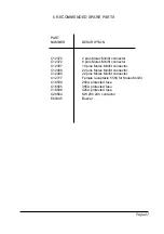
Page 27: ...Molex Minifit connector C12397 10 pins Molex Minifit connector C12408 20 pins Molex Minifit connector C12499 22 pins Molex Minifit connector C12777 Female receptacle 5556 for Molex Minifit C16530 250A protected fuse C16505 355A protected fuse C16506 425A protected fuse C29564 SW 200 24V contactor E60305 Buzzer ...

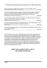
Page 28: ...eck every _________________________________________________ 3 MONTHS Check the mechanical operation of the Contactor s Moving contacts should be free to move without restriction Check every _________________________________________________ 3 MONTHS Checks should be carried out by qualified personnel only and each replacement part used should be original Beware of NOT ORIGINAL PARTS The installatio...

Page 29: ...Page 29 ...

Page 30: ...TRUZIONE APPARECCHIATURE ELETTRONICHE OLEODINAMICHE INDUSTRIALI COSTRUZIONE APPARECCHIATURE ELETTRONICHE OLEODINAMICHE INDUSTRIALI COSTRUZIONE APPARECCHIATURE ELETTRONICHE OLEODINAMICHE INDUSTRIALI 42028 POVIGLIO R E Via Parma 59 ITALIA Tel 39 0522 960050 r a Fax 39 0522 960259 e mail zapi zapispa it COMBI SEM 1 OPERATING AND USER MANUAL ...

Reviews: