


ADBZP0AB - CAN TILLER - User Manual
Page - 3/18
Contents
1
MAIN FEATURES .................................................................................................................4
2
TECHNICAL SPECIFICATION .............................................................................................5
2.1
Digital inputs ...............................................................................................................5
2.1.1
Digital inputs technical details.......................................................................5
2.1.2
Microswitches ...............................................................................................5
2.2
Analog inputs ..............................................................................................................5
3
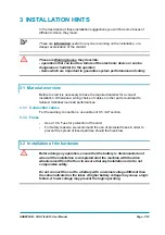
INSTALLATION HINTS.........................................................................................................7
3.1
Material overview........................................................................................................7
3.1.1
Connection cables ........................................................................................7
3.1.2
Fuses ............................................................................................................7
3.2
Installation of the hardware.........................................................................................7
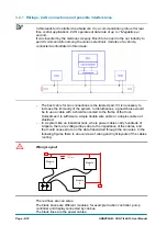
3.2.1
Wirings: CAN connections and possible interferences .................................8
3.2.2
Wirings: I/O connections .............................................................................10
3.2.3
Insulation of truck frame..............................................................................10
3.3
Protection and safety features ..................................................................................10
3.3.1
Protection features......................................................................................10
3.3.2
Safety Features...........................................................................................10
3.4
EMC..........................................................................................................................11
4
DESCRIPTION OF THE CONNECTORS............................................................................13
4.1
A connector: Molex Minifit, 16 pins ...........................................................................13
4.2
B connector: Molex Minifit, 6 pins .............................................................................13
4.3
C connector: Molex Minifit, 8 pins .............................................................................13
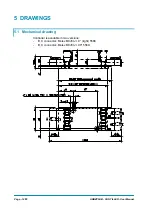
5
DRAWINGS .........................................................................................................................14
5.1
Mechanical drawing ..................................................................................................14
5.2
Functional drawing....................................................................................................16
6
RECOMMENDED SPARE PARTS .....................................................................................17
7
PERIODIC MAINTENANCE TO BE REPEATED AT TIMES INDICATED .........................18
APPROVAL SIGNS
COMPANY FUNCTION
INITIALS
SIGN
PROJECT MANAGER
FG
TECHNICAL ELECTRONIC
MANAGER VISA
PP
SALES MANAGER VISA
MC
Publication N°:
ADBZP0AB
Edition:
March 2009