Zapi CAN TILLER User Manual Download Page 10

Page - 10/18 

ADBZP0AB - CAN TILLER - User Manual 

4


Can advantages 

The complexity of today systems needs more and more data, signal and 
information must flow from a node to another. CAN is the solution to different 
problems that arise from this complexity 
- simplified design (readily available, multi sourced components and tools) 
- lower costs (less and smaller cables ) 
- improved reliability (fewer connections) 
- analysis of problems improved (easy connection with a pc to read the data 
flowing through the cable). 

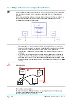
3.2.2  Wirings: I/O connections 

After crimping the cable, verify that all strands are entrapped in the wire 
barrel. 

Verify that all the crimped contacts are completely inserted on the connector 
cavities. 

U


A cable connected to the wrong pin can lead to short circuits and failure; 
so, before turning on the truck for the first time, verify with a multimeter the 
continuity between the starting point and the end of a signal wire. 

For information about the mating connector pin assignment see the 
paragraph “description of the connectors”. 

3.2.3  Insulation of truck frame 

U


As stated by EN-1175 “Safety of machinery – Industrial truck”, chapter 5.7, 
“there shall be no electrical connection to the truck frame”. So the truck 
frame has to be isolated from any electrical potential of the truck power 
line. 

3.3  Protection and safety features 

3.3.1 Protection 

features 

Connection Errors: 

All inputs are protected against connection errors. 

External agents: 

The controller is protected against dust and the spray of liquid to a degree of 
protection meeting IP54. 

3.3.2 Safety 

Features 

U


ZAPI devices are designed according to the prEN954-1 specifications for 
safety related parts of control system and to UNI EN1175-1 norm. 
 
The safety of the machine is strongly related to installation; length, layout 
and screening of electrical connections have to be carefully designed. 
ZAPI is always available to cooperate with the customer in order to evaluate 

Summary of Contents for CAN TILLER

Page 1: ...ECTRONIC OLEODYNAMIC INDUSTRIAL EQUIPMENTS CONSTRUCTION Via Parma 59 42028 POVIGLIO RE ITALY Tel 39 0522 960050 r a Fax 39 0522 960259 e mail zapi zapispa it web www zapispa it EN User Manual CAN TILL...

Page 2: ...hanges or improvements to its products at any time and without notice The present publication reflects the characteristics of the product described at the moment of distribution The publication theref...

Page 3: ...3 2 3 Insulation of truck frame 10 3 3 Protection and safety features 10 3 3 1 Protection features 10 3 3 2 Safety Features 10 3 4 EMC 11 4 DESCRIPTION OF THE CONNECTORS 13 4 1 A connector Molex Minif...

Page 4: ...nd sending them to other Can network s nodes via Can Bus Twelve digital inputs at 24 V 12 V Four analog inputs with potentiometer s output in the 0 5 V range or 0 12 V range Two inputs which can be us...

Page 5: ...V Input impedance 4 25 kohm 0 3 kohm Input impedance 7 4 kohm 0 4 kohm only for DI4 and DI5 DI12 AI5 Commutation threshold 5 V 0 5 V Input impedance 47 3 kohm 2 4 kohm DI13 AI6 Commutation threshold O...

Page 6: ...nd NPOT CAN 12 The potentiometer supply available are 12 V or 5 V the maximum load current provided by the internal voltage regulator is 100 mA so the minimum load is 47 PPOT 5 V 120 PPOT 12 V The sta...

Page 7: ...g choice of cables or other parts could lead to failures misbehaviour bad performances 3 1 1 Connection cables For the auxiliary connections use cables of 0 5 mm section 3 1 2 Fuses Use a 10 A Fuse fo...

Page 8: ...system to disturbances a good choice would be to use a cable with a shield connected to the frame of the truck Sometimes it is sufficient a simple double wire cable or a duplex cable not shielded In...

Page 9: ...pump motor controller and a third module works with less current the best way to deal this configuration is to create a common ground point star configuration U Correct Layout Note Module 1 power Mod...

Page 10: ...ity between the starting point and the end of a signal wire For information about the mating connector pin assignment see the paragraph description of the connectors 3 2 3 Insulation of truck frame U...

Page 11: ...prevent the propagation of that energy we talk about conduction issues when guiding structures such as wires and cables are involved radiated emissions issues when it is studied the propagation of el...

Page 12: ...b and work on it B SHIELDING enclosing contactor and controller in a shielded box using shielded cables C LAYOUT a good layout of the cables can minimize the antenna effect cables running nearby the t...

Page 13: ...th analog input A14 BATT Batt short circuit to CNB 5 A15 COMMON Positive of all the digital inputs A16 BATT Batt 4 2 B connector Molex Minifit 6 pins B1 CAN LOW Low level CAN BUS voltage I O B2 BATT B...

Page 14: ...Page 14 18 ADBZP0AB CAN TILLER User Manual 5 DRAWINGS 5 1 Mechanical drawing Controller is available in two versions B C connector Molex Minifit Jr 0 right 5566 B C connector Molex Minifit Jr 90 5569...

Page 15: ...ADBZP0AB CAN TILLER User Manual Page 15 18 It is also possible to have the card inside an encapsulating resin case A A...

Page 16: ...Page 16 18 ADBZP0AB CAN TILLER User Manual 5 2 Functional drawing...

Page 17: ...number Description C12404 Connector 16 pos Receptacle Housing Dual Row P N 0039012160 C12359 Connector 6 pos Receptacle Housing Dual Row P N 0039012060 C12414 Connector 8 pos Receptacle Housing Dual...

Page 18: ...or any problem that arises from wiring methods that differs from information included in this Manual During periodic checks if a technician finds any situation that could cause damage or compromise sa...

Reviews: