background image

Warning!

 The adjustment conditions for

this appliance are located on the label or

rating plate.

Warning!

 The manufacturer is not

responsible for damages caused by an

installation which does not agree with the
instructions in the manual.

Installation environment:

• This appliance is not connected to a combus-

tion products evacuation device.

• Only install the appliance in a room with suffi-

cient ventilation.

• Keep natural ventilation holes open or install a

cooker hood.

• There must be a 130 cm² minimum opening

in the built-in cabinet.

The use of a gas cooking appliance results in
the production of heat and moisture in the room
in which it is installed. Ensure that the kitchen is
well ventilated: keep natural ventilation holes
open or install a mechanical ventilation device
(mechanical extractor hood). Prolonged inten-
sive use of the appliance may call for additional
ventilation, for example opening a window, or
more effective ventilation, for example increas-
ing the level of mechanical ventilation where
present.

Gas connection

The gas supply ramp is on the rear side of the
control panel.

Warning!

 Do not use rubber flexible pipes.

Warning!


Before the gas connection,

disconnect the mains plug from the

mains socket or deactivate the fuse in the
fuse box. Close the primary valve of the
gas supply.

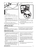
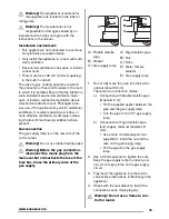
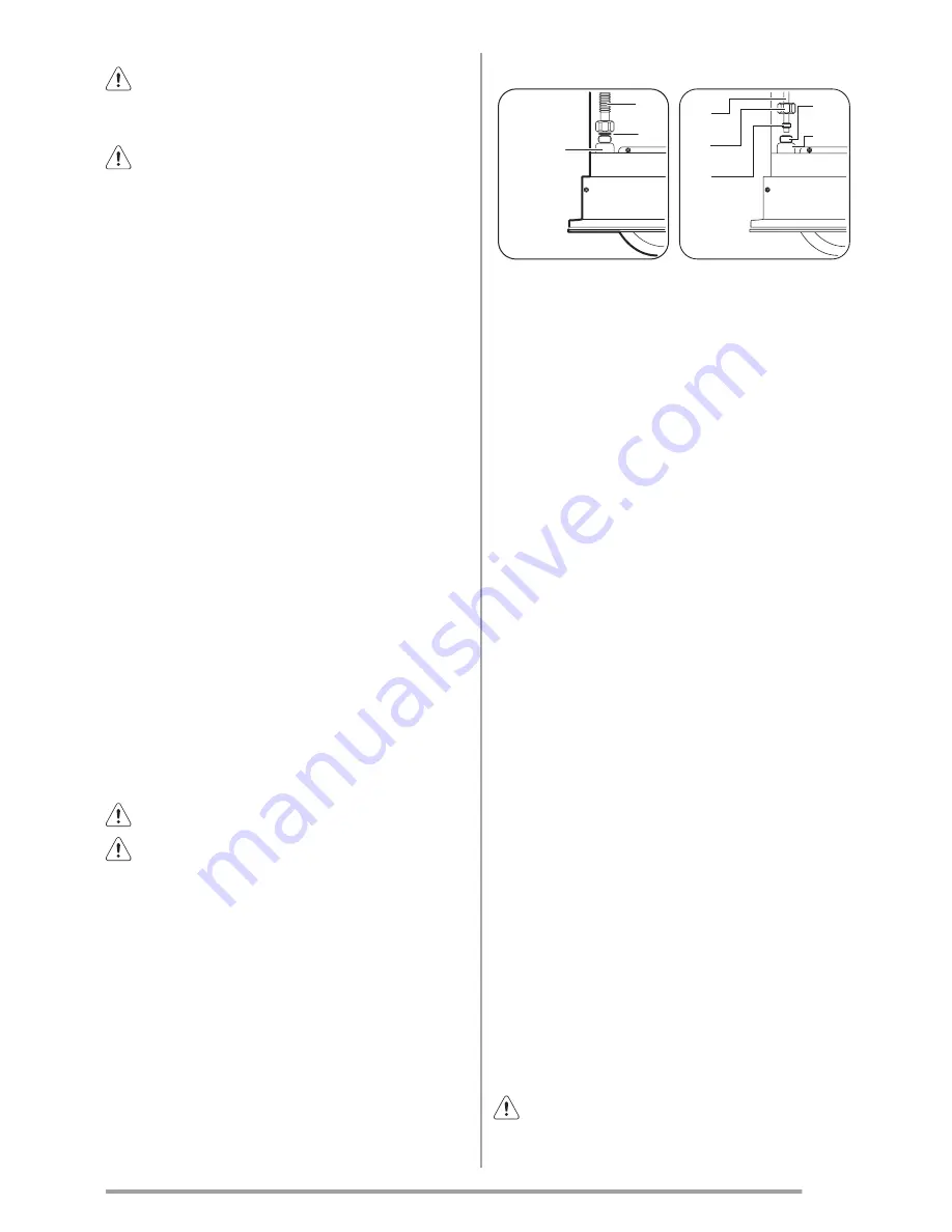
A
B

C

A
B
C

D
E

A) Flexible metallic

pipe

B) Gasket

C) Gas supply ramp

A) Rigid metallic pipe

B) Nut

C) Olive

D) Male / female

adapter

E) Gas supply ramp

1.

Do not fully move the oven into the built-in
cabinet (about 30 cm).
There are two connection modes:

a)

Connection with flexible metallic pipe
(maximum 2 m):

• Put the supplied gasket between the

pipe and the gas supply ramp.

• Turn the pipe to the 1/2“ gas supply

ramp.

b)

Connection with rigid metallic pipe
(soft copper, minimum diameter: 8
mm):

• Use a male / female adapter (not

supplied) to install the nut and the
olive on the gas supply ramp.

• Put the pipe into the gas supply

ramp.

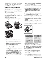
2.

Use a 22 mm spanner to tighten the nuts.
Keep the gas supply ramp in correct posi-
tion, do not apply force on the gas supply
circuit.

3.

Fully insert the appliance into the built-in
cabinet. See instructions in “Building-in the
appliance”.

4.

Check with the leak detection fluid if the
connection seal is made properly.

Warning!


Do not use a flame to con-

trol for leaks!


15

www.zanussi.com

Summary of Contents for ZOG11311

Page 1: ...EN User manual Oven ZOG11311 GB ...

Page 2: ...efully read the supplied instructions The manufacturer is not responsible if an incor rect installation and use causes injuries and damages Always keep the instructions with the appliance for future reference Children and vulnerable people safety Warning Risk of suffocation injury or permanent disability This appliance can be used by children aged from 8 years and above and persons with reduced ph...

Page 3: ... pull the appliance by the handle Keep the minimum distance from the other appliances and units Make sure that the appliance is installed be low and adjacent safe structures The sides of the appliance must stay adjacent to appliances or to units with the same height Electrical connection Warning Risk of fire and electrical shock All electrical connections should be made by a qualified electrician ...

Page 4: ...Be careful when you open the appliance door while the appliance is in operation Hot air can release Do not operate the appliance with wet hands or when it has contact with water Do not apply pressure on the open door Do not use the appliance as a work surface or as a storage surface Always keep the appliance door closed when the appliance is in operation Open the appliance door carefully The use o...

Page 5: ...metal objects If you use an oven spray obey the safety in structions on the packaging Do not clean the catalytic enamel if applica ble with any kind of detergent Internal light The type of light bulb or halogen lamp used for this appliance is only for household appli ances Do not use it for house lighting Warning Risk of electrical shock Before replacing the lamp disconnect the appliance from the ...

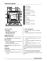
Page 6: ...rning Refer to the Safety chapters Initial cleaning Remove all accessories and removable shelf supports if applicable Clean the appliance before first use Important Refer to the chapter Care and cleaning Preheating Preheat the empty appliance to burn off the re maining grease 1 Set the function and the maximum tem perature 2 Let the appliance operate for 60 90 mi nutes 3 Set the function and the m...

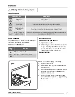
Page 7: ...on control knob Gas oven control knob Sym bol Function The oven burner is off min 240 Range of temperature adjustment Gas oven cooking Ignition of oven gas burner 1 Open the oven door 2 Press the gas oven control knob and turn it to Keep it pushed for some seconds but no more than 15 seconds Do not re lease it until the flame comes on Manual ignition If there is no power supply temporarily 1 Open ...

Page 8: ... you may place directly on the grill pan food such as fish liver and kid neys To minimise splashing you should thoroughly dry food before grilling Brush lean meats and fish lightly with a little oil or melted butter to keep them moist during cooking You may place accompaniments such as to matoes and mushrooms underneath the grid when grilling meats You should use the top runner position when toast...

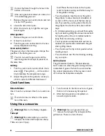
Page 9: ...nues to operate until the temperature in the appliance cools down Helpful hints and tips The appliance has four shelf levels Count the shelf levels from the bottom of the appliance floor The appliance has a special system which circulates the air and constantly recycles the steam With this system you can cook in a steamy environment and keep the food soft inside and crusty outside It decreases the...

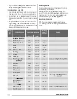
Page 10: ... this appliance Gas Oven Cooking The time does not include preheating Always preheat the empty oven for 10 mi nutes Weig ht kg TYPE OF DISH Gas Oven Cooking Cooking time in minutes Notes Temp C level MEAT POULTRY 1 Beef with bone min 2 or 3 40 1 Beef without bone 190 2 or 3 50 1 Lamb min 2 or 3 40 50 1 Pork 175 2 or 3 50 1 2 Chicken Rabbit 210 2 or 3 70 80 1 Duckling 190 2 or 3 80 1 Turkey 180 2 o...

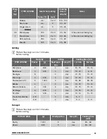
Page 11: ...ing time min TYPE OF DISH Pieces g Shelf posi tion Temp C 1st side 2nd side Fillet steaks 4 800 4 max 12 15 12 14 Beef steaks 4 600 4 max 10 12 6 8 Sausages 8 4 max 12 15 10 12 Pork chops 4 600 4 max 12 16 12 14 Chicken cut in 2 2 1000 4 max 30 35 25 30 Kebabs 4 4 max 10 15 10 12 Breast of chicken 4 400 4 max 12 15 12 14 Hamburger 6 600 4 max 13 15 12 14 Fish fillet 4 400 4 max 12 14 10 12 Toasted...

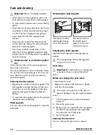
Page 12: ...round the frame of the oven cavity Do not use the appliance if the door gasket is damaged Contact the Service Centre To clean the door gasket refer to the general information about cleaning Shelf supports You can remove the shelf supports to clean the side walls Removing the shelf supports Pull the front of the shelf support away from the side wall 1 2 Pull the rear end of the shelf support away f...

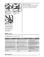
Page 13: ...pliance does not operate The appliance is not activated Activate the appliance Refer to the chapter Daily Use The appliance does not operate The fuse in the fuse box is re leased Do a check of the fuse If the fuse is released more than one time contact a qualified electrician The oven lamp does not operate The oven lamp is defective Replace the oven lamp Steam and condensation collect on the food ...

Page 14: ...minal gas flow Reduced gas power By pass nee dle Nominal gas pressure 1 100 mm kW g h kW 1 100 mm mbar Natural gas G20 114 2 7 1 0 Reg 20 Liquid gas G30 G31 078 2 5 182 1 0 52 28 30 37 Installation Warning Refer to the Safety chapters Safety for installation These installation instructions are for authorized persons only Warning Let only authorized persons gas and electricity do the installation c...

Page 15: ...amp is on the rear side of the control panel Warning Do not use rubber flexible pipes Warning Before the gas connection disconnect the mains plug from the mains socket or deactivate the fuse in the fuse box Close the primary valve of the gas supply A B C A B C D E A Flexible metallic pipe B Gasket C Gas supply ramp A Rigid metallic pipe B Nut C Olive D Male female adapter E Gas supply ramp 1 Do no...

Page 16: ...d remove it Re place it with the necessary one see table Gas Oven Burner Data 5 Assemble the gas oven burner in opposite sequence 6 Replace the gas type sticker near the gas supply ramp with the one related to the new gas type supplied with the injector kit Warning A primary air adjustment of the gas oven burner is not necessary Minimum level adjustment of the gas oven burner 1 Disconnect the main...

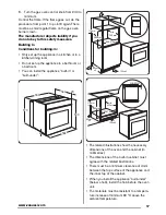
Page 17: ...pliance built in or built under 570 594 590 560 540 20 2 130cm min 550mm 110mm 580mm 560 570mm 65cm x2 560 570mm 593mm min 4mm 65cm x2 110mm min 550mm 130cm The related illustrations show the necessary dimensions of the oven and the cabinet in millimetres The dimensions of the built in cabinet must agree with the related illustrations There must be a minimum clearance of 4 mm between the top surfa...

Page 18: ...r the section of the cable refer to the total power on the rating plate and to the table Total power Section of the cable maximum 1380 W 3 x 0 75 mm maximum 2300 W 3 x 1 mm maximum 3680 W 3 x 1 5 mm The earth cord green yellow cable must be 2 cm longer than phase and neutral cables blue and brown cables Environment concerns The symbol on the product or on its packaging indicates that this product ...

Page 19: ...19 www zanussi com ...

Page 20: ...www zanussi com shop 397305401 A 122013 ...

Reviews: