background image


You will receive an e-mail with a link activating your user account. After activation, log in at 

https://cloud.supla.org

  and  enter  data  given  in  the  registration  form.  After  login,  you  have 

an access to all necessary data required for configuration. 
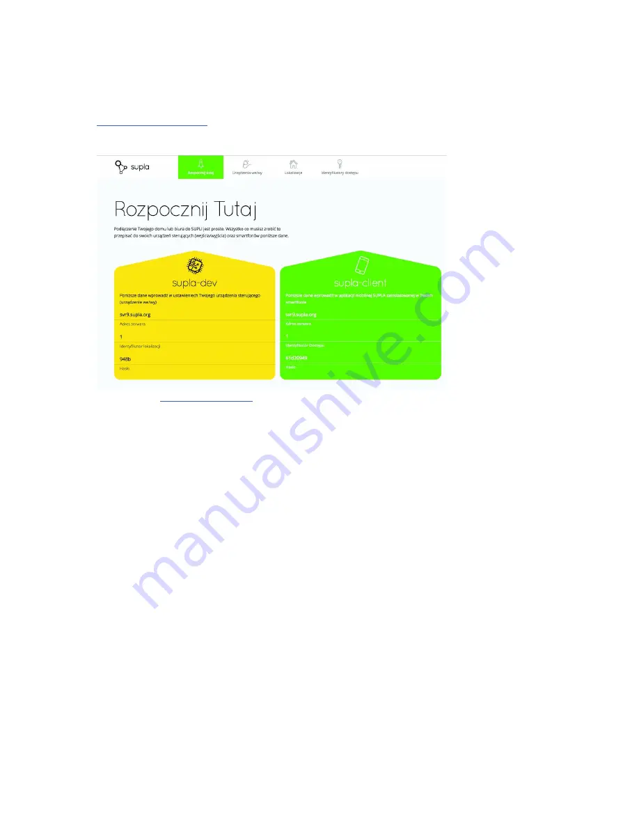


* screenshot of 

https://cloud.supla.org

 subpage 

“Start here”


If  you  already  have  a  user  account  at  cloud.supla.org  server,  you  can  enter  the  next  step 
regarding the connection and configuration of ROW-01 module. 


Configuration ROW-01 module 

 
After  the  device  has  been  switched  on,  the  software  controls  the  settings.  In  case  the 
settings  have  not  been  implemented  yet,  the  module  switches  automatically  into  the 
configuration mode. It is signalled by means of a flashing LED diode. In other cases, press the 

CONFIG

  push  button  for  a  longer  time  (available  in  a  slot)  for  a  minimum  of  5  seconds  to 

enter the configuration mode. In this mode the module operates as a Wi-Fi access point and 
is visible in the Wi-

Fi network under the name of “ZAMEL

-ROW-

01”


Summary of Contents for ROW-01

Page 1: ...1 ZAMEL ROW 01 FITTING INSTRUCTION MANUAL...

Page 2: ...2 Content Technical data 4 Installation remarks 5 Mounting 5 Registry 8 ROW 01 module configuration 9 Installation and configuration of SUPLA on smartphones or tablets 13...

Page 3: ...sure there is no voltage on the connection cables by means of a special measuring equipment before mounting We did our best to make the product operates properly But if you have any remarks regarding...

Page 4: ...er of output channels 1 Relay contact parameters voltage free NO contact 1 x NO 5A 250 VAC Maximum output load 1 x 5A 250 V AC incandescent and halogen lamps 750 W CFL lamps 250 W LED lamps 60 W Numbe...

Page 5: ...inputs are designed to cooperate with monostable or bistable switches By default the IN1 input operates in the monostable mode doorbells and the IN2 input in the bistable mode for standard lighting s...

Page 6: ...roper circuit Remove the switch and disconnect the wires 2 Connect the device to power supply in accordance with one of the below presented installing diagram and switch on the power supply from the m...

Page 7: ...7 Diagram no 2 includes device mounting behind a monostable switch doorbell...

Page 8: ...nt yet register now and follow the below presented steps Registration and system usage are free of charge Open https cloud supla org website and click Create an account screenshot of https cloud supla...

Page 9: ...regarding the connection and configuration of ROW 01 module Configuration ROW 01 module After the device has been switched on the software controls the settings In case the settings have not been imp...

Page 10: ...ed to Wi Fi networks and has an installed browser After a connection to the W Fi ZAMEL ROW 01 has been completed successfully you can open the browser and enter the following address http 192 168 1 in...

Page 11: ...a dev which is displayed after logging in at https cloud supla org Rewrite data from the yellow field into the red ones It means rewrite Server address into Server field Location ID into Location ID a...

Page 12: ...ction It is signalled by a flashing LED 2 flashes 1 second In case of a positive connection the device establishes a connection with SUPLA server It is signalled by a flashing LED 1 flash 1 second The...

Page 13: ...on smartphones or tablets In case of smartphones tablets with Android system operation open Google Play store next find the SUPLA application and install it In case of iPhone or iPad open AppStore nex...

Page 14: ...ata in the green form supla client which is displayed after login in at https cloud supla org Rewrite data from the green form into the red fields After entering all settings correctly the application...

Reviews: