background image

GiMBAL CONTROL ON PROACTION

There are two modes to control the Gimbal through ProAction: Follow Mode and Global Mode.

Switch on the ProAction on a flat and stable surface. Do not move, sway or shake the ProAc-

tion during initialization. After initialization, the gimbal will boot up normally in either Follow 

or Global Mode, depending on user settings on the left-hand switches of the ProAction. 

Once the gimbal is on, it begins an automatic self-check by rotating about the yaw axis. At 

this time, the power indicator will be on as well. At the same time the control status LED will 

blink green and blue alternately.   

When the self-check (start-up) process is complete, the Control Status LED will grow solid 

blue. The user can switch freely between Follow Mode and Global Mode without powering 

off the gimbal. 

FOLLOW MODE
In Follow Mode, the camera lens moves in the direction of ProAction. The user can only 

manipulate the pitch direction through Gimbal Control Stick on the right.

If the Gimbal Control Stick moves upward, the camera lens will trim itself up. If the Gimbal 

Control Stick moves downward, the camera lens will trim itself down.

NOTICE: In Follow Mode, the camera lens will move in the direction of the Gimbal. At this 

time, the Gimbal will take control of itself in the Yaw direction and the user can only control 

the Gimbal in the Pitch direction.

NOTICE: The Yaw Axis inside the Gimbal will rotate in the direction of ProAction Frame. Any 

manipulation in the Yaw direction is invalid, in other words, the user can only control the Pitch 

direction.

GLOBAL MODE
In Global Mode, the camera lens sticks to a fixed direction instead of following the movement 

of the ProAction Frame. The user can control the Yaw and Pitch Direction through Gimbal 

Control Stick.

If the Gimbal Control Stick moves upward, the camera lens will trim itself up. If the Gimbal 

Control Stick moves downward, the camera lens will trim itself down. If the Gimbal Control 

Stick turns right, the camera lens will trim itself to the right. If the Gimbal Control Stick turns 

left, the camera lens will trim itself to the left.

DOUBLE HANDS OPERATING:

Grip the left and right handles of the ProAction™ with both hands. The Power and Mode 

Selection Switch is on the left side, while the Gimbal Control Stick is on the right side.

NOTICE: Once the ProAction™ is started up, no matter which mode it is in, the default mode 

is Double Hands Operating. The Control Status Indicator on center carrying handle will be 

solid red. The user can ONLY take control of the gimbal through Gimbal Control Stick on the 

right side.

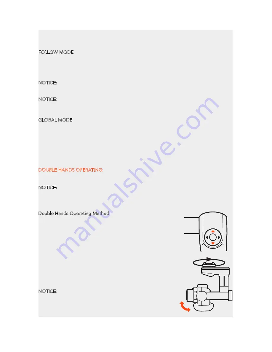
Double Hands Operating Method

In the Follow Mode, the camera lens track the ProAction™ in 

Yaw axis. The user can only control the pitch direction through 

Gimbal Control Stick on the right.

Move the Gimbal Control Stick upward to trim the camera lens 

up. Move the Gimbal Control Stick downward to trim the 

camera lens down.

In the Global Mode, the camera lens does not move in the 

direction of the ProAction™ Frame but sticks to a fixed 

direction. The user can control both the Yaw and Pitch 

directions through Gimbal Control Stick.

Move the Gimbal Control Stick upward/downward to trim the 

camera lens up/down. Move the Gimbal Control Stick to the 

left/right to trim the camera lens left/right.

NOTICE: When in the Follow Mode, the Gimbal Control Stick 

can't control the GB603 in Yaw axis. When in the Global 

Mode, the Gimbal Control Stick can control the GB603 in

Pitch and Yaw axes.

16

Summary of Contents for Proaction CGO4

Page 1: ...V11172015 ...

Page 2: ...TE BALANCE SETTING THE LIGHT SENSITIVITY COMPENSATING THE EXPOSURE SPECIFYING THE APERTURE SHUTTER SPEED MENU SETTING INTRODUCTION GROUND IMAGING SYSTEM APP DOWNLOADING ATTACHING CGO4 GIMBAL CAMERA TO PROACTION BINDING CGO4 GIMBAL CAMERA TO APP GIMBAL CONTROL ON PROACTION APP INTERFACE PHOTO TAKING AND VIDEO RECORDING CAMERA MODE INTRODUCTION ADJUSTING THE WHITE BALANCE COMPENSATING THE EXPOSURE S...

Page 3: ...rms and reshapes the boundaries of aerial imaging creation Through the user friendly control app interface in the ST24 the CGO4 becomes an incredible tool to realize the highest levels of aerial photographic and video graphic imagery SPECIFICATIONS PROACTION DIMENSIONS 14 17x10 04x14 57in 360x255x370mm WEIGHT without battery 52 91oz 1 5kg BATTERY WEIGHT 7 72oz 219g INCLUDED BATTERY 4S 14 4V 0 3C 2...

Page 4: ...e to operate the product correctly can result in damage to the product property and or cause serious injury WARNING This is a sophisticated consumer product It must be operated with caution and common sense and requires some basic mechanical ability Failure to operate this product in a safe and responsible manner could result in damage to the product property and or cause serious injury This produ...

Page 5: ...ar a window Do not try to repair the CGO4 gimbal camera by yourself Do not attempt to operate CGO4 gimbal camera in areas with potential magnetic and or radio interference including areas nearby broadcast towers power transmission stations high voltage power lines etc Do not operate the Gimbal in the rain Do not expose the Gimbal to fire sources Do not touch or move the Gimbal until the initializa...

Page 6: ...PROACTION Power Status Indication First Level Low Voltage Battery Warning LED blinking green slowly Second Level Low Voltage Battery Warning LED blinking green quickly CGO4 CAMERA ST24 and gimbal camera not connected LED blinking green ST24 and mobile device connected LED blinking blue CGO4 Wi Fi malfunction LED blinking red CGO4 GIMBAL Firmware update in progress LED blinking blue Firmware update...

Page 7: ... The default Model type is Multi copter Tap the H920 CGO4 icon and press OK to enter the flight control interface NOTE The pre set model in the Model Select interface cannot be deleted NOTE The pre set model can only be bound to one multi copter If the user wants to bind to the other copters press and hold the H920 CGO4 icon select copy on the pop up menu Wait for a few seconds and then tap the ne...

Page 8: ...g down The distance between the slider and the middle position decides the velocity rate the further distance the higher velocity it would be Gimbal Yaw Control There is a gimbal yaw mode switch on ST24 S2 When the switch position is up and middle the gimbal camera is in Follow Mode The yaw control of the gimbal camera is now disabled The gimbal camera will adjust its yaw direction according to th...

Page 9: ... to go back to the flight control interface BINDING H920 MULTICOPTER TO THE ST12 TEAM MODE STEP 1 Power on the ST12 and tap RC on the main interface STEP 2 Tap Model Select and if required press OK to bypass any pop up warning alerts STEP 3 Tap to create a new model and if required press OK to bypass any pop up warnings alerts STEP 4 Tap Flight Settings and if required press OK to bypass any pop u...

Page 10: ...is time the yaw control is activated The gimbal camera will adjust its yaw direction according to the aircraft s movements When the switch position is down the gimbal camera is in Global Mode The Aileron Roll Control and Elevator Pitch Control of the right hand stick take control of the CGO4 in yaw and pitch directions NOTICE When the CGO4 is attached to the TORNADO H920 the control knob K6 is act...

Page 11: ...on located on the right side of ST24 You ll hear an audible indication from ST24 each time the recording starts stops And while video is recording there will be a red dot next to the video recording timer near the upper right hand corner of ST24 CAUTION If the video is being recorded on ProAction repress the video recording button to end the process otherwise the video is unable to be saved A To t...

Page 12: ...r Speed cannot be adjusted separately under P mode it can only be controlled through the Union Picker APERTURE PRIORITY AE MODE The shutter speed is automatically determined by the aperture value you set SHUTTER PRIORITY AE MODE The aperture value is automatically determined by the shutter speed you set MANUAL EXPOSURE MODE The exposure is adjusted by the aperture value and the shutter speed which...

Page 13: ... effect of the set aperture value and shutter speed will not be visible on the recording screen NOTE If the photographer wants to highlight the background set a relatively high aperture value if the photographer wants a soft background set a relatively low level NOTICE It will operate as AWB during motion picture recording AWB Automatic Adjustment Daylight When taking pictures outdoors under a cle...

Page 14: ...k shooting set a relatively low shutter speed When CGO4 gimbal camera is in Aperture Priority AE Mode the camera automatically optimizes the shutter speed for the brightness of the subject When CG04 gimbal camera is in shutter priority AE Mode the camera automatically optimizes the aperture value for the brightness of the subject When CGO4 gimbal camera is in Manual Exposure Mode the photographer ...

Page 15: ...llows you to select the aspect ratio of the pictures to suit printing or the playback method NOTICE The ends of the recorded pictures may be cut at printing so check before printing 4 3 3 2 16 9 Aspect Ratio of a 4 3 TV 4608x3456 16M 3264X2448 8M 2336X1752 4M 1 1 Aspect Ratio of a 35mm film camera Aspect Ratio of a high definition TV etc Spare aspect ratio 4608X3072 14M 3264X2176 7M 2336X1560 3 5M...

Page 16: ...is the method used to focus on the subject on the center of the screen and measure the whole screen evenly Spot This is the method to measure the subject in the spot metering target Taking pictures using Burst Mode Pictures taken with a burst speed of SH will be recorded as a single burst group Slide the Menu and Select Driving Mode Focus on the subject and take a picture Changing the burst speed ...

Page 17: ... camera so that you can see exactly what your camera sees with a live HD video feed right on your mobile device It makes you feel as though the camera is right in your hands CAUTION If the user wants to take photos or videos through ProAction CGO4 APP should be downloaded beforehand STEP 1 Make Wi Fi connection between your mobile device Select the correct Wi Fi SSID and enter the password 1234567...

Page 18: ...bal Control Stick turns right the camera lens will trim itself to the right If the Gimbal Control Stick turns left the camera lens will trim itself to the left DOUBLE HANDS OPERATING Grip the left and right handles of the ProAction with both hands The Power and Mode Selection Switch is on the left side while the Gimbal Control Stick is on the right side NOTICE Once the ProAction is started up no m...

Page 19: ...the right side of the ProAction is disabled in Pitch direction NOTICE When the user holds the ProAction with single hand in the Global Mode the user can control the camera in the Yaw direction through the Gimbal Control Stick Single Hand Operating Method Roll the Pitch Control Wheel forward to move the camera pitch angle downward and roll the Pitch Control Wheel backward to move the camera pitch a...

Page 20: ...l photos TO START STOP VIDEO RECORDING Press button and you can start to record the video If you have successfully entered video recording the button will turn red and a video recording timer will appear on the top right corner of the screen CAUTION If the video is being recorded repress the video recording button to end the process before powering off the gimbal or the video is unable to be saved...

Page 21: ...ightness of the subject You can take picture with greater freedom by changing various settings in the Menu Settings CAUTION The Aperture and Shutter Speed cannot be adjusted separately under P mode it can only be controlled through the Union Picker APERTURE PRIORITY AE MODE The shutter speed is automatically determined by the aperture value you set SHUTTER PRIORITY AE MODE When you set the shutter...

Page 22: ... under the incandescent lights AWB Daylight Cloudy Halogon Shade Exposure Compensation 1 3 EV STEP 5EV 3 EV for motion picture Exposure Accuracy 1 3 EV Maximum Aperture F3 5 Wide F5 6 Tele Minimum Aperture F22 NOTE If the photographer wants to capture fast move subjects set a relatively high shutter speed if the photographer wants to track shooting set a relatively low shutter speed When CGO4 gimb...

Page 23: ... the right hand column and tap Camera S STEP 2 A camera setting bar will pop up on the screen STEP 3 Slide the Camera ON OFF switch to the right to turn on the camera STEP 4 Slide the Camera ON OFF switch to the left to turn off the camera GUIDELINESS When there are obstacles the position judgment of the photographer may be biased The guidelines function can help to correct their judgment in the h...

Page 24: ...finer the detail of the pictures will appear even when they are printed onto large sheets 16M 8M 4M IMAGE FORMAT This sets the file format for the pictures you take Fine Standard RAW fine RAW standard RAW VIDEO QUALITY This sets up the picture quality for motion pictures OPTIONS MP4 30P 100Mbps 4K MP4 24P 100Mbps 4K MP4 60P 28Mbps 4K MP4 30P 20M Angle of view Focal Length Wide f 14mm 75 Tele f 42m...

Page 25: ...ng the burst speed Pictures taken with a burst speed of SH will be recorded as a single burst group Slide the Menu and Select Driving Mode Focus on the subject and take a picture NORMAL When the shutter button is pressed only one picture is recorded BURST Recordings are made in succession while the shutter button is pressed AF MODE This allows the focusing method that suits the positions and numbe...

Page 26: ...or one which is unfit to fly e g due to dirt water penetration coarse particles oil or a model which has not been correctly or completely assembled or if the main components exhibit visible damage defects or missing parts Damage and or injury as well as violation of legal regulations caused by operating the model in a magnetic field e g high voltage lines electricity transformer stations radio tow...

Page 27: ...scope of use defined by Yuneec Electric Aviation as improper This product is designed for both professional use and personal private use The national and international laws and regulations in force as the time of taking off must be adhered to 25 ...

Page 28: ...the separation between the equipment and receiver Connect the equipment into an outlet on a circuit different from that to which the receiver is connected Consult the dealer or an experienced radio TV technician for help This device complies with Part 15 of the FCC Rules Operation is subject to the following two conditions 1 This device may not cause harmful interference and 2 this device must acc...

Page 29: ...intention des autres utilisateurs il faut choisir le type d antenne et son gain de sorte que la puissance isotrope rayonnée équivalente p i r e ne dépasse pas l intensité nécessaire à l établissement d une communication satisfaisante User manuals for transmitters equipped with detachable antennas shall also contain the following notice in a conspicuous location This radio transmitter identify the ...

Reviews: