


14
Sn
Input
specification
Code
InP
Input spec.
InP
Input spec.
0
K
20
Cu50
1
S
21
Pt100
2
stock
22
0
~
75mV
3
T
26
0
~
80ohm resistor input
4
E
27
0
~
400ohm resistor input
5
J
28
0
~
20mV voltage input
6
B
29
0
~
100mV voltage input
7
N
30
0
~
60mV voltage input
8
WRe3-WRe25
31
0
~
1V voltage input
9
WRe5-WRe26
32
0.2
~
1V voltage input
10
extended
input
specification
33
1
~
5V voltage input
12
F2 radiation type
pyrometer
34
0
~
5V voltage input
15
4
~
20mA (installed I4
in MIO)
35
-20
~
+20mV
16
0
~
20mA (I4 is
installed in MIO)
0
~
10V (I31 is
installed in MIO)
36
2
~
10V
37
0
~
20V
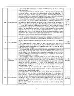
When Sn=10, It means extended input is used. Like R,
WRe325,WR3520,BA1,BA2,G,F2,0-5V, 1-5V.
0
~
37
dIP
Radix point
position
Four formats (0, 0.0, 0.00, 0.000) are selectable
dIP=0, display format is 0000, no radix point
dIP=1, display format is 000.0
dIP=2, display format is 00.00
dIP=3, display format is 0.000
Note 1: For thermocouples or RTD input, only 0 or 0.0 is selectable, and the
internal resolution is 0.1.
dIP only affect the display, and has no affect to the accuracy of measurement
or control.
0
~
3
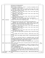
dIL
Signal scale
low limit
Define scale low limit of input. It is also the low limit of external set value,
transmittion output and light bar display.
E.g.:pressure transmitter is used, 1-5v input,as for 1V input is 0,5V is 1MPa,
hope to be resolution as 0.001MPa. Then you need to set as follows:
Sn=33(1-5v input)
Dip=3(0.000format)
dIL=0.000(input low limit is 1V)
dIH=1.000(input high limit is 5V)
-1999
~
+9999
units or
1
℃
dIH
Signal scale
high limit
Define scale high limit of input. It is also the high limit of external set value,
retransmission output and light bar display.
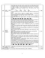
Sc
Input offset
Sc is used to compensate the error caused by transducer, input signal, or auto
cold junction compensation of thermocouple.
PV_after_compensation=PV_before_compen Scb
E.g.:if input is remaining same, Sc=0.0C, PV=500.0C, when Sc is 10.0, then
PV is 510.0C. Sc is usually 0.
-1.99
~
+4000
℃


