background image

SMART POSITIONER 
TMP-3000 


PRODUCT MANUAL


Ver. 1.03 


are not covered by the warranty. 


Please contact us for further information on product warranty.   
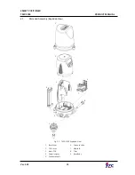
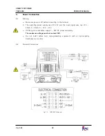


2.


Product Description 

2.1 

General


The TMP-3000 Smart Positioner not only precisely controls the valve opening according 
to  the  current  signal  of  4  ~  20mA  DC  input  from  the  controller  or  the  central  control 
room,  but  also  performs  the  auto  calibration  by  the  computation  action  of  the  built-in 
high  performance  microprocessor  and  PD  control.  It  is  a  highly  reliable  positioner  that 
performs various powerful functions such as optimum control. 
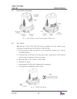
 

2.2 

Main Features and Functions 


In case of Fail Freeze optional product, it maintains the current valve position without 
any  additional  equipment  such  as  lockup  valve  or  solenoid  valve  in  case  of  input 
signal and pneumatic failure. 


Back  light  function  LCD  is  attached  so  you  can  check  the  status  of  the  positioner 
directly in the field. 


Four  adjustment  buttons  and  unique  functions  of  the  buttons  are  applied  in  the 
same way throughout the firmware, so it is very easy to use. 


The  initialization  time  is  very  short,  which  minimizes  the  change  of  valve  stroke  in 
case of temporary power failure and improves system stability. 


Very strong against vibration and can be used in extremely high vibration areas. 


The change in supply pressure during use has almost no effect on the adjustability 
of the positioner. 


Auto calibration is very simple, so first time users can handle the product easily. 


Compact size makes it easy to attach to small actuators. 


Very low air consumption which allows large plants to reduce their operating costs. 


The valve system can be stabilized by outputting an analog feedback signal. 


Variable valve flow control characteristics such as Linear, Quick Open, Equal % can be 
changed. 


It is possible to implement special flow control characteristics by specifying 16 points 
at user's discretion. 


You  can  minimize  valve  leakage  by  setting  the  sealing  function  of  Tight  Shut-Off  / 
On. 


Half-interval control (Split Range) is available such as 4 ~ 12mA and 12 ~ 20Ma. 


You can change Zero and Span freely through Hand Calibration function. 


By manual operation, valve can be operated arbitrarily irrespective of input signal, so 

Summary of Contents for TMP-3000

Page 1: ...SMART POSITIONER PRODUCT MANUAL TMP 3000 VERSION 1 03...

Page 2: ...10 Dimensions 13 3 Installation 14 3 1 Safety 14 3 2 Tools required for Installation 14 3 3 TMP 3000 Installation 14 3 3 1 TMP 3000 Installation Example 14 3 3 2 Installing 15 3 3 3 Warning 17 4 Pneum...

Page 3: ...nt PV_END 26 6 7 3 Zero Point TR_ZERO and End Point TR_END 26 6 7 4 Normal Reverse Feedback Signal TR NORM REVS 27 6 8 Valve Mode VALVE 27 6 8 1 Acting Adjustment ACT RA dA 28 6 8 2 Characteristic Adj...

Page 4: ...his is called original point Zero This manual cannot be reproduced or reused for any purpose without our approval If any problem arises that is not described in this manual please contact us immediate...

Page 5: ...same way throughout the firmware so it is very easy to use The initialization time is very short which minimizes the change of valve stroke in case of temporary power failure and improves system stabi...

Page 6: ...e so it can be used stably for a long time even in a corrosive atmosphere The internal structure is very simple and modular so there is little possibility of failure and maintenance is simple It is eq...

Page 7: ...roduct 24VDC 10 INPUT SIGNAL The range of the input current signal is indicated OPERATING TEMP The ambient temperature range in which the positioner can operate is indicated SUPPLY PRESSURE Indicates...

Page 8: ...3 4 5 6 1 Pneumatic Output S D Single Acting Single Double Acting Double 2 Explosion Protection N Non Explosion 3 Conduit Pneumatic Connection G M16 1 5P G1 8 4 Flow Capacity 1 2 20LPM 50LPM 5 Option...

Page 9: ...LPM Filtering Size particle size 5 Micron Air Connection G1 8 6mm Tube Operating Temp 10 60 C 14 140 F Conduit 2 M16 1 5P Stroke 5 40mm Ingress Protection IP67 Vibration 100Hz No resonance up to 6G B...

Page 10: ...SMART POSITIONER TMP 3000 PRODUCT MANUAL Ver 1 03 10 2 6 Certificate and Approvals Electromagnetic Compatibility EMC EMC directive 2014 30 EC from April 2016 EC Directive for CE conformity marking...

Page 11: ...L Ver 1 03 11 2 7 Parts and Assembly Exploded View Fig 2 1 TMP 3000 Exploded View 1 Base Cover 6 Solenoid Valve 2 PCB Cover 7 Manifold 3 Main PCB 8 Filter 4 Potentiometer 9 Base Body 5 Feedback Shaft...

Page 12: ...e the followings to clean the filter All input signals to valves actuators and other peripherals pneumatics etc must be completely stopped Disconnect the control valve from the system with a bypass va...

Page 13: ...SMART POSITIONER TMP 3000 PRODUCT MANUAL Ver 1 03 13 2 10 Dimensions Fig 2 4 TMP 3000 Dimensions...

Page 14: ...tuator Disconnect the control valve from the system with a bypass valve or other similar device to prevent shutdown of the entire system 3 2 Tools required for Installation Hexagonal wrench set Screw...

Page 15: ...with the installation Positioner Feedback Shaft 3 3 2 Installing 1 Check actuator stroke max 40mm and screw size M26X1 5P on actuator Please check if it is possible to assemble with the feedback shaf...

Page 16: ...Actuator adapter on top of the actuator Fig 3 3 TMP 3000 Feedback Shaft Assembly 3 Using a flat head screwdriver tighten the M6x1 0P male thread of the actuator to the female thread of the coupling at...

Page 17: ...te it in the desired direction and tighten both wrench bolts The head of the wrench bolt is 3mm Fig 3 5 TMP 3000 Fixing the Body 3 3 3 Warning After installation temporarily connect the pneumatic regu...

Page 18: ...st 10 C below the ambient temperature dew point Filter out foreign substances with 5 micron filter Do not include oil or lubricant in the air Must comply with ISO 8573 1 or ISA 7 0 01 This positioner...

Page 19: ...single acting spring return type actuator connect the OUT1 port to the actuator s pneumatic port Fig 4 1 Single Acting Actuator Pneumatic Piping Example 4 4 2 Double Acting Actuator For double acting...

Page 20: ...operating power supply uses DC 24V and the input signal uses one of 4 20mA 0 20mA 0 5V 0 10V If PTM option is available supply 9 28V DC power separately The maximum voltage must not exceed 30V Do not...

Page 21: ...ent is input to the positioner the RUN mode is displayed on the LCD window after about 0 5 second as shown in the figure RUN indicates that the positioner is adjusting the valve stroke according to th...

Page 22: ...e you have installed the positioner on the actuator 6 4 1 Auto 1 Calibration Mode AUTO1 AUTO1 resets only the zero point and the end point Auto calibration is performed without changing any other prev...

Page 23: ...rn to RUN mode the positioner is controlled by the input current signal again ENTER 6 seconds ENTER UP DOWN Press UP or DOWN button if the above is not displayed ESC ESC 6 6 Parameter Mode PARAM By pe...

Page 24: ...tton if the above is not displayed Press UP or DOWN button if the above is not displayed UP DOWN ENTER ESC 3 times 6 6 2 PT1 PT2 Values The PT control value is a parameter that indicates the minimum l...

Page 25: ...tween the control signal and actual valve stem operation Large values can cause oscillations 6 6 5 PERIOD Time PERIOD It means the control cycle inside the positioner Basically it checks the current p...

Page 26: ...valve and PV_END is the mode to change the end point 6 7 3 Zero Point TR_ZERO and End Point TR_END TR_ZERO is the zero point of the feedback output signal and TR_END is the mode in which the end point...

Page 27: ...flow characteristic mode CHAR You can change user characteristics mode USER SET You can set the direct acting actuator seal mode TSHUT OP You can set the dynamic actuator airtight mode TSHUT CL You c...

Page 28: ...e from three options Linear LIN user setting USR Equal percentage EQ and Quick open QO 6 8 3 User defining flow Characteristics USER SET In case positioner requires a specific characteristic the valve...

Page 29: ...ENTER UP DOWN ENTER or ENTER UP DOWN ENTER or ENTER UP DOWN ENTER or ENTER UP DOWN ENTER or ENTER ESC 2 times 2 21 point setting ENTER ENTER ENTER Press UP or DOWN button if the above is not displayed...

Page 30: ...uator force to prevent leakage of the valve 6 8 6 Custom Zero Setting Mode CST ZERO CST ZERO is the value of the analog input signal corresponding to the start point of set value for Split Range Contr...

Page 31: ...r example if the analog input signal is selected 4 to 20mA and CST ZERO is set to 0 and CST END is set to 50 the valve opening will be 0 to 100 when the input signal is in the 4 to 12mA range The devi...

Page 32: ...ew Mode Normal means 0 at 4mA and 100 at 20mA VM REVS It means View Mode Reverse 100 at 4mA and 0 at 20mA VM dIZ View Mode Digital means to display the raw data of the position value converted from th...

Page 33: ...ops and this message is immediately displayed on the LCD window Make sure air pressure is being supplied to the positioner properly RNG ERR If the operation length of the feedback lever is too small d...

Page 34: ...SMART POSITIONER TMP 3000 PRODUCT MANUAL Ver 1 03 34 8 LCD Operating Order...

Page 35: ...ech Co Ltd Address 81 Hwanggeum ro 89 beon gil Yangchon eup Gimpo si Gyeonggi do South Korea Postal Code 10048 Telephone 031 986 8545 FAX 070 4170 4927 E mail ytc sales rotork com Website http www ytc...

Reviews: