background image

youngmangroup.com

4

StairMax 600 

Assembly Procedure

1


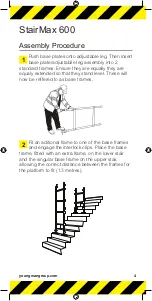
Push base plates onto adjustable leg. Then insert 
base plate/adjustabile leg assembly into 2 

standard frames. Ensure they are equally they are 
equaly extended so that they stand level. These will 
now be reffered to as base frames.


2

Fit an aditional frame to one of  the base frames 
and engage the interlock clips. Place the base 

frame, fitted with an extra frame, on the lower stair 
and the singular base frame on the upper stair, 
allowing the correct distance between the frames for 
the platform to fit (1.3 metres).

Summary of Contents for StairMAX 600

Page 1: ...StairMAX Aluminium Tower 600 700 850 Climbing Rung 3T Through The Trapdoor Method User Guide Edition July 2008 TM...

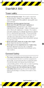
Page 2: ...on this tower whilst those likely to excert moderate sideways force should be carried out with due care Never use boxes steps etc to gain extra height Never reach too far out to one side If the tower...

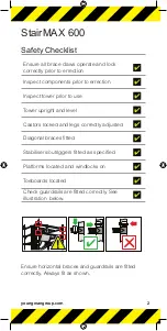
Page 3: ...Inspect tower prior to use Tower upright and level Castors locked and legs correctly adjusted Diagonal braces fitted Stabilisers outriggers fitted as specified Platforms located and windlocks on Toeb...

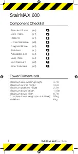
Page 4: ...ce x6 Diagonal Brace x2 Stabiliser x1 Adjustable Leg x4 Base Plate x4 End Toeboard x2 Side Toeboard x2 Tower Dimensions Maximum safe working height 3 7m Maximum overall height 3 5m Maximum platform he...

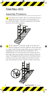
Page 5: ...ually they are equaly extended so that they stand level These will now be reffered to as base frames 2 Fit an aditional frame to one of the base frames and engage the interlock clips Place the base fr...

Page 6: ...m to the top rungs of the two end frames Make sure all four platform end hooks are in contact with the top rungs then secure in place by engaging the hook latches see illustration Fit a standard frame...

Page 7: ...applications in addition to any method of stabilisation used Please contact your supplier ro hire shop for details If stabiliser s are required they must be fitted to the corner s of the end frame on...

Page 8: ...the bottom rung of each base frame i e 75kg at each end Please contact your supplier or hire shop for details B The tower is positioned up against a wall on one side and a stabiliser is fitted on the...

Page 9: ...tructions to ensure your system is erected easily and safely using the 3T Through The Trapdoor method The law requires that personnel errecting dismanatling or altering towers must be competent Any pe...

Page 10: ...load is 275kg 606lb per platform level Towers must always be climbing from the inside using the built in ladder during assembly and use It is recomended that towers should be tied to a solid structure...

Page 11: ...und clearnce for stabilisers outriggers contact your supplier for advice Ballast must be of solid materials ie not water or loose sand and should not be positioned to overload individual legs Ballast...

Page 12: ...ches in motion telegraph wires whistle 6 25 31 11 14 Gale Force Walking is difficult 8 39 46 17 21 Beware of open ended buildings which can cause funneling effect Do not abuse equipment Damaged or inc...

Page 13: ...tying in a tower please contact your supplier or Youngman Maintenance Storage Transport All components and their parts should be regularly inspected to identify damage particularly to joints Lost or b...

Page 14: ...nd Frame 2 2 4 Rung Guardrail Frame 1 0m high x 0 85m wide 1 1 7 Rung Span Frame 1 75m high x 0 85 wide 2 3 Trap Door Deck 2 2 Horizontal Brace 5 9 Diagonal Brace 5 6 Side Toeboard 2 2 End Toeboard 2...

Page 15: ...4 Rung Guardrail frame 1 0m high x 0 85m wide 1 1 7 Rung Span Frame 2 0m high x 0 85 wide 1 2 Trap Door Deck 2 2 Horizontal Brace 5 9 Diagonal Brace 6 8 Side Toeboard 2 2 End Toeboard 2 2 Toeboard Hol...

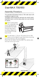
Page 16: ...at base plates are used instead of castors 1 Push 4 base plates onto adjustable legs Insert adjustable leg assemblies into Walk through base frame as shown Repeat for second Walk through base frame 2...

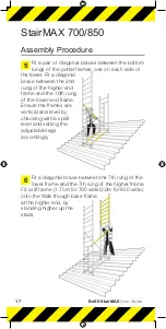
Page 17: ...he climbing side above the 5th rung of the portal frame with the claw facing outwards The frame will now be self supporting Note All locking claws must be open before fitting 4 Position the second por...

Page 18: ...the higher end frame and the 10th rung of the lower end frame Ensure the frames are vertical and level by checking with a spirit level and setting the adjustable legs accordingly 6 Fit a diagonal bra...

Page 19: ...he end frame Where possible the Stabilisers must also have a minimum outstand of 1 2m 8 Fit a temporary trapdoor deck on the 7th rung of the upper frame as shown Climb up the inside of the tower and f...

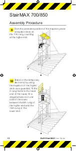
Page 20: ...rapdoor deck on the 11th rung counting at the higher end 10 Stand on the temporary deck and by using the trapdoor of the higher deck as a guardrail fit the 4 rung frame to the lower end of the tower F...

Page 21: ...next height the 4 rung frame at the lower end should be replaced with a lift frame 1 75m for 700 2 0m for 850 The 4 rung frame should then be positioned at the higher end of te tower Diagonal braces...

Page 22: ...e edge of the deck on all sides 850 StairMax Lock yellow plastic toeboard clips over rung and deck claw as shown Position as A on right hand deck claw On other side of the working plaform position the...

Page 23: ...youngmangroup com 22 Stabilisers StairMax 600 StairMAX 700 850 1 5m Min 1 2m Min 1 2m Min Min Min...

Page 24: ...on about this product or any other products and services please contact Youngman Group Ltd The Causeway Maldon Essex CM9 4LJ United Kingdom t 44 0 1621 745900 f 44 0 1621 859845 e sales youngmangroup...

Reviews: