


64
output power of
transmitter
(
W
)
150kHz -80MHz
P
d
=
1
5
.
3
80MHz-800MHz
P
d
=
3
5
.
3
800MHz-2.5GHz
P
d
=
3
7
0.01
0.35
0.12
0.23
0.1
1.11
0.37
0.74
1
3.50
1.17
2.34
10
11.07
3.69
7.38
100
35.00
11.67
23.34
If the rated maximum output power of the transmitter is not included in the values given
above, can be estimated by using the corresponding column isolation distance
equation. In the equation P is the nominal maximum output power of transmitter
manufacturers are given, measured in watts.
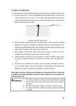
If the system image severely disturbed affect diagnosis, it is necessary to set the
device away from the noise source or install the external RF transmission power noise
filter the noise reduced to an acceptable level.
Be careful 1 :
In 80MHz-800MHz, using a higher frequency formula
Be careful 2:
These guidelines do not apply in all cases. The material
structure, objects and people can absorb and reflect electromagnetic waves, thus
affecting the electromagnetic propagation.
Table 5
Fundamental characteristics
Scanning mode: the mode of operation of an ultrasonic diagnostic device, including
a series of ultrasonic pulses that generate scanning lines that do not follow the same
acoustic path.
Scanning mode
Parameter
B mode
Gain
:
0-100 tunable
Maximal acoustic output
:
10-100% tunable
Depth
:
— C5-2Fs probe
≥
30cm
— C5-2Ks probe
≥
30cm
— L11-4Ks probe
≥
14cm
— L11-4Gs probe
≥
14cm
— C8-5Ks probe
≥
14cm
— E10-4Ks probe
≥
14cm
M mode
C mode
Power mode
PW mode


