background image

YO Airflow  Pro

User guide

v1.0

page 12/26

3. The device is on. Screw it back together
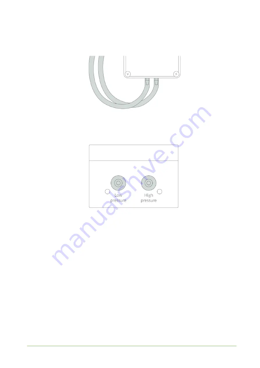
4. Insert the silicone tubing onto the sensor inputs.

Figure 10

Connecting silicone tubing instructions.

Important!

The sensors must be placed according to the following diagram, i.e. the sensor measuring the higher

pressure must be placed on the right side and the one measuring the lower pressure on the left side:

Figure 11

Connecting silicone tubing side view instructions.

Important to avoid breaking the device!

In case of removing silicone tubes it is necessary to cut off the tubes from the connectors i.e. with a
sharp knife. First tubes must be cut off on the edge of the sensor with high or low pressure, then cut
off the rest of the silicon tube located along the black sensor. Then take off the rest of the silicon tube
gently without breaking the sensor.

REV 1.0

www.yo

sensi

.

io

Summary of Contents for YO Airflow Pro

Page 1: ...YO Airflow Pro User guide v1 0...

Page 2: ...YO Airflow Pro User guide v1 0 page 2 26 Release notes Released Version Key changes 05 09 2022 1 0 Initial release REV 1 0 www yosensi io...

Page 3: ...erature and relative humidity 8 Battery condition 8 Installation 9 Package contents 9 Safety precautions 9 Installation guide 9 Operation 12 IoT system components 12 Device configuration 13 Configurab...

Page 4: ...used for control and monitor airflow Figure 1 Device top view Device sticker placed on the right side of the device enclosure contains information about model version LoRaWAN region and 3 parameters...

Page 5: ...ing incorrectly power and memory LoRaWAN communication failed to receive an acknowledgement from LoRaWAN Server within specified timeout Single flash White LoRaWAN communication LoRaWAN frame sent con...

Page 6: ...gure 3 Dimensions of the device PHYSICAL SPECIFICATION Dimensions Height 42 mm Width 88 mm Depth 64 mm Colour Light grey Mounting method Horizontal Vertical can be screwed to the wall Enclosure materi...

Page 7: ...ferential pressure 500 Pa to 500 Pa 0 1 Pa 3 reading temperature dependent Temperature internal 40 C to 125 C 0 2 C from 5 C to 60 C Relative humidity internal 0 to 100 2 at 20 RH to 80 RH Differentia...

Page 8: ...perature and relative humidity are measured by sensors placed inside the device enclosure These measurements can be used to monitor if the device is working in recommended conditions Figure 5 Internal...

Page 9: ...dition Battery voltage is used to monitor its condition to spot anomalies like sudden drop or its current condition based on voltage drop over time in comparison to initial voltage rating Figure 7 Bat...

Page 10: ...operations near inside electronics Be careful while handling the device dropping it may cause damage that will affect the sensors and other electronics inside When installing the device on the wall re...

Page 11: ...de 1 Unscrew the device remove 4 screws from the enclosure Figure 8 Device opening instructions 2 Place three LR6 batteries in the device according to the polarity indicated on the battery holder Figu...

Page 12: ...side and the one measuring the lower pressure on the left side Figure 11 Connecting silicone tubing side view instructions Important to avoid breaking the device In case of removing silicone tubes it...

Page 13: ...e with their use The sensor measuring the higher pressure must be placed where the higher pressure occurs The sensor measuring the lower pressure must be placed where the pressure is lower Figure 12 C...

Page 14: ...y 2 Gateway device similar to routers equipped with a LoRa concentrator that receives LoRa packets and send them to the Internet connected server 3 Server in most cases a cloud based service where dat...

Page 15: ...ct to the LoRaWAN ble generic bluetooth settings device dynamic individual configuration for a specific device the structure of this section is different for each device Sample configuration file for...

Page 16: ...UI Extended Unique Identifier 8 B HEX predefined R W appeui Application EUI 8 B HEX predefined R W appkey Application Key 16 B HEX predefined R W trials Join request trials 1 9 3 R W lorawan abp devad...

Page 17: ...or setting the device in ABP or OTAA mode deveui appskey predefined addresses and keys these parameters are generated using multiple IDs specific to the particular MCU and are unique for each device t...

Page 18: ...0 3 911 7 MHz channels 40 47 6 Sub band 7 911 9 913 3 MHz channels 48 55 7 Sub band 8 915 5 914 9 MHz channels 56 63 8 AU915 Sub band 1 915 2 916 6 MHz channels 0 7 1 2 R W Sub band 2 916 8 918 2 MHz...

Page 19: ...LI are available at https yosensi io support CLI_datasheet pdf Command help view yosensi cli tool_v3 1 0_win exe upload_dev_config help usage yosensi cli tool upload_dev_config h mac positional argume...

Page 20: ...gration instructions 1 Go to app yosensi io and log in 2 You ll see the default organization view To switch to another organization click on the user avatar in the right top corner and select Switch O...

Page 21: ...fter activation in Yosensi Management Platform by changing the Node configuration Click on the link in the Node Name column Go to the KEYS tab and switch Lora Type from OTAA to ABP and fill in the Dev...

Page 22: ...own server you have to decode the payload specific to each device To do this you need a payload decoder which can be downloaded from Payload decoder Extended documentation of the protocol can be foun...

Page 23: ...ement relative humidity 0x10 0x00 0x01 0x42 type 4 prec 0 md s 0 addr_len 0 meas_len 2 val 66 66 Fourth measurement accelerometer angles 0x41 0x00 0x05 0xFE 0xF5 0x00 0x00 0x00 0xBD type 16 prec 1 md...

Page 24: ...YO Airflow Pro User guide v1 0 page 24 26 Compliance statements REV 1 0 www yosensi io...

Page 25: ...YO Airflow Pro User guide v1 0 page 25 26 REV 1 0 www yosensi io...

Page 26: ...YO Airflow Pro User guide v1 0 page 26 26 Revision history Date Version Changes 05 09 2022 1 0 Initial release REV 1 0 www yosensi io...

Reviews: