


JOHNSON CONTROLS
137
SECTION 7 – UNIT CONTROLS
FORM 150.72-ICOM6
ISSUE DATE: 08/03/2022
7
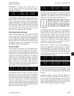
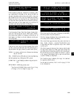
COOLING RANGE 42.0 +/- 2.0 DEGF
HEATING RANGE 122.0 +/- 2.0 DEGF
SYS 1 SETPOINT
70 +/- 3 PSIG
SYS 2 SETPOINT
70 +/- 3 PSIG
REMOTE SETPOINT
44.0 DEGF
AMBIENT AIR TEMP
74.8 DEGF
LEAD SYSTEM
SYS 2
EVAPORATOR PUMP
ON
EVAPORATOR HEATER
OFF
ACTIVE REMOTE CONTROL
NONE
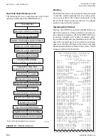
LAST DEFROST SYS X DURATION XXXS
TIME TO SYS X DEFROST
XX MIN
BIVALENT DELAY REMAINING XX MIN
UNIT XXX.X AMPS
X.X VOLTS
SOFTWARE VERSION
C.M02.13.00
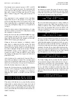
SYSTEM 1 DATA
COMP STATUS 1=OFF 2=OFF 3=OFF
RUN TIME
0- 0- 0- 0 D-H-M-S
TIME YYYYYYY 0- 0- 0- 0 D-H-M-S
LAST STATE
YYYYYYY
SUCTION PRESSURE
105 PSIG
DISCHARGE PRESSURE
315 PSIG
SUCTION TEMPERATURE 46.0 DEGF
SAT SUCTION TEMP
34.0 DEGF
SUCTION SUPERHEAT
12.0 DEGF
COOLER INLET REFRIG 31.6 DEGF
DEFROST TEMPERATURE 52.8 DEGF
LIQUID LINE SOLENOID
OFF
MODE SOLENOID
OFF
HOT GAS BYPASS VALVE
OFF
CONDENSER FAN STAGE
OFF
EEV OUTPUT
0.0 %
SYSTEM
XXX.X AMPS X.X VOLTS
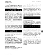
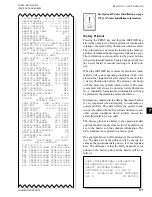
SYSTEM 2 DATA
COMP STATUS 1=ON, 2=OFF, 3=ON
RUN TIME
0-0-1-46 D-H-M-S
TIME YYYYYYY
0-0-0-0 D-H-M-S
LAST STATE
YYYYYYY
SUCTION PRESSURE
110 PSIG
DISCHARGE PRESSURE
320 PSIG
SUCTION TEMPERATURE 49.3 DEGF
SAT SUCTION TEMP
36.0 DEGF
SUCTION SUPERHEAT
13.3 DEGF
COOLER INLET REFRIG 31.6 DEGF
DEFROST TEMPERATURE 52.8 DEGF
LIQUID LINE SOLENOID
ON
MODE SOLENOID
ON
CONDENSER FAN STAGE
3
EEV OUTPUT
63.2%
SYSTEM
XXX.X AMPS X.X VOLTS
DAILY SCHEDULE
S M T W T F S
*=HOLIDAY
SUN START=00:00AM STOP=00:00AM
MON START=00:00AM STOP=00:00AM
TUE START=00:00AM STOP=00:00AM
WED START=00:00AM STOP=00:00AM
THU START=00:00AM STOP=00:00AM
FRI START=00:00AM STOP=00:00AM
SAT START=00:00AM STOP=00:00AM
HOL START=00:00AM STOP=00:00AM
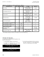
See Optional Printer Installation on page
195 for Printer Installation information.
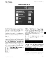
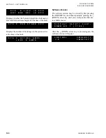
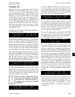
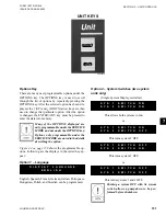
History Printout
Pressing the PRINT key and then the HISTORY key
allows the operator to obtain a printout of information
relating to the last 9 Safety Shutdowns which occurred.
The information is stored at the instant of the fault, re-
gardless of whether the fault caused a lockout to occur.
The information is also not affected by power failures
(long-term internal memory battery backup is built into
the circuit board) or manual resetting of a fault lock-
out.
When the HISTORY key is pressed, a printout is trans-
mitted of all system operating conditions which were
stored at the “instant the fault occurred” for each of the
9 Safety Shutdowns buffers. The printout will begin
with the most recent fault which occurred. The most
recent fault will always be stored as Safety Shutdown
No. 1. identically formatted fault information will then
be printed for the remaining safety shutdowns.
Information contained in the Safety Shutdown buffers
is very important when attempting to troubleshoot a
system problem. This data reflects the system condi-
tions at the instant the fault occurred and often reveals
other system conditions which actually caused the
safety threshold to be exceeded.
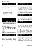
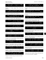
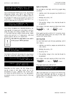
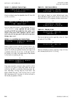
The history printout is similar to the operational data
printout shown in the previous section. The differences
are in the header and the schedule information. The
daily schedule is not printed in a history print.
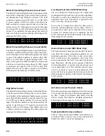
One example history buffer printout is shown follow-
ing. The data part of the printout will be exactly the
same as the operational data print so it is not repeated
here. The difference is that the Daily Schedule is not
printed in the history print and the header will be as
follows.
YORK INTERNATIONAL CORPORATION
MILLENNIUM LIQUID CHILLER
SAFETY SHUTDOWN NUMBER 1
SHUTDOWN @ 3:56PM 29 SEP 07
SYS 1 HIGH DSCH PRESS SHUTDOWN
SYS 2 NO FAULTS


