


JOHNSON CONTROLS
105
SECTION 5 – TECHNICAL DATA
FORM 150.72-ICOM6
ISSUE DATE: 08/03/2022
55
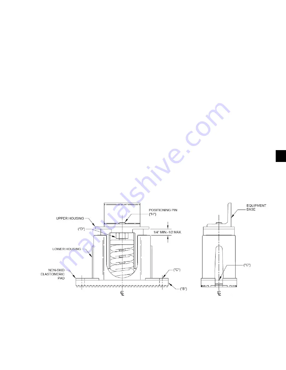
1 IN. DEFLECTION SPRING ISOLATORS
INSTALLATION INSTRUCTIONS
1. Read instructions in their entirety before begin-
ning installation.
2. Isolators are shipped fully assembled and are to be
positioned in accordance with the submittal draw-
ings or as otherwise recommended.
3.
Set isolators on floor, housekeeping pad or sub-
base, ensuring that all isolators centerlines match
the equipment mounting holes. The VMC group
recommends that the isolator base (“B”) be in-
stalled on a level surface. Shim or grout as re-
quired, leveling all isolator bases to the same
elevation (1/4 in. maximum difference can be tol
-
erated).
4. Bolt or anchor all isolators to supporting structure
utilizing base slotted holes (“C”).
5. Place equipment on top of isolators making sure
that mounting holes of the equipment line up with
isolator positioning pin (“H”).
6. The adjustment process can only begin after the
equipment or machine is at its full operating
weight.
7. Adjust each isolator in sequence by turning spring
adjusting bolt (“D”) one full counterclockwise
turn at a time. Repeat this procedure on all isola-
tors, one at a time.
8. Continue adjusting each isolator until a minimum
of 1/4 in. clearance is achieved between the lower
housing and upper housing. (See drawing below).
9. Fine adjust isolators to level equipment.
10. Installation is complete.
LD13790


