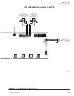
background image

JOHNSON CONTROLS

2

FORM 160.76-PW5 

ISSUE DATE: 09/06/2019

This equipment is a relatively complicated apparatus. 

During rigging, installation, operation, maintenance, 

or service, individuals may be exposed to certain com-

ponents or conditions including, but not limited to: 

heavy objects, refrigerants, materials under pressure, 

rotating components, and both high and low voltage. 

Each of these items has the potential, if misused or 

handled improperly, to cause bodily injury or death. It 

is the obligation and responsibility of rigging, instal-

lation, and operating/service personnel to identify and 

recognize these inherent hazards, protect themselves, 

and proceed safely in completing their tasks. Failure 

to comply with any of these requirements could result 

in serious damage to the equipment and the property in 

IMPORTANT!

READ BEFORE PROCEEDING!

GENERAL SAFETY GUIDELINES

which it is situated, as well as severe personal injury or 

death to themselves and people at the site.
This document is intended for use by owner-authorized 

rigging, installation, and operating/service personnel. It 

is expected that these individuals possess independent 

training that will enable them to perform their assigned 

tasks properly and safely. It is essential that, prior to 

performing any task on this equipment, this individual 

shall have read and understood the on-product labels, 

this document and any referenced materials. This in-

dividual shall also be familiar with and comply with 

all applicable industry and governmental standards and 

regulations pertaining to the task in question.

SAFETY SYMBOLS

The following symbols are used in this document to alert the reader to specific situations:

Indicates a possible hazardous situation 

which will result in death or serious injury 

if proper care is not taken.

Indicates a potentially hazardous situa-

tion which will result in possible injuries 

or damage to equipment if proper care is 

not taken.

Identifies a hazard which could lead to 

damage to the machine, damage to other 

equipment and/or environmental pollu-

tion if proper care is not taken or instruc-

tions and are not followed.

Highlights additional information useful 

to the technician in completing the work 

being performed properly.

External wiring, unless specified as an optional connection in the manufacturer’s product line, is not 

to be connected inside the control cabinet. Devices such as relays, switches, transducers and controls 

and any external wiring must not be installed inside the micro panel. All wiring must be in accor-

dance with Johnson Controls’ published specifications and must be performed only by a qualified 

electrician. Johnson Controls will NOT be responsible for damage/problems resulting from improper 

connections to the controls or application of improper control signals. Failure to follow this warn-

ing will void the manufacturer’s warranty and cause serious damage to property or personal injury.

Summary of Contents for YK

Page 1: ...NEER _______________________________________________ REFERENCE DATE ________ APPROVAL DATE ________ CONSTRUCTION DATE _______ Supersedes 160 76 PW5 719 Form 160 76 PW5 919 WIRING DIAGRAM MODEL YK STYL...

Page 2: ...this document and any referenced materials This in dividual shall also be familiar with and comply with all applicable industry and governmental standards and regulations pertaining to the task in que...

Page 3: ...lity of these documents to the equipment If there is any question regarding the applicability of these documents rig ging lifting and operating service personnel should verify whether the equipment ha...

Page 4: ...ected to Terminals 1 and 7 line 32 See Note 9 Remote run stop line 32 is operative only in the remote operating mode 9 The device contact rating is 5 mA at 115 VAC NOTES 10 The maximum allowable curre...

Page 5: ...Starter TB1 or 1TB LEGEND 1HTR 1 Phase 1000 W Oil Heater 1LEP Low Evaporator Pressure Provided by Evap Pressure Transducer 1OL 2T Protector 346 V and 600 V Units Only 1T Class 2 Power Supply Transfor...

Page 6: ...34 4 J34 10 J34 2 2 J34 6 2 5 162 J34 3 VGD MOTOR OPTION FOR COMPR W VGD ONLY FIELD L2 X L1 2 3 158 160 159 OPEN FIELD CLOSE 3 4 7 2 OPEN CLOSE 4 6 2 MOV MOV 158 MOV MOV 6 7 PRV MOTOR 3 25 21 CONTROL...

Page 7: ...J35 2 I O BOARD 031 01743 001 CONT D VGD REMOTE LCHLT SETPOINT OFFSET PWM SIGNAL REMOTE CURRENT LIMIT SETPOINT PWM SIGNAL REMOTE LOCAL CYCLING DEVICES THRUST BEARING SWITCH OPEN ON FAULT CHILLED LIQU...

Page 8: ...159 4 6 2 3 158 MOV MOV 7 PRV MOTOR 3 4 7 2 MOV MOV 6 PE STARTER INTERLOCK CLOSES AT FULL VOLTAGE CE VERSION FOR ALL COMPR EXCEPT K7 GRN YEL LT BLU RED 14 J33 1 1 GROUNDED CONDUCTOR 3BR 6 AMP 250V CKT...

Page 9: ...NE 41 20 AMP 250V LITTLEFUSE FLQ 20 2FU 164 K17 J34 5 J34 6 P34 14 J33 9 J34 15 17 P34 13 5 AMP 250V BUSS ABC 5 J33 1 3FU RED LT BLU GRN YEL ELEMENTARY DIAGRAM UL VERSION FOR K7 COMPR ONLY 2 3 L2 SUPR...

Page 10: ...NOTE 12 V EN PWM WHT RED BLK J20 1 J20 2 J20 3 TO MICRO BOARD CUSTOMER SUPPLIED 3 PHASE OIL PUMP POWER SUPPLY SEE CHART ON FIELD CONNECTIONS DIAGRAM ON PANEL DOOR L1 L2 L3 313B 313C 306B ROW 3 ROW 4...

Page 11: ...1 TB8 LTC I O 031 02895 313B 2 P31 313 1 14 LTC I O 031 02895 J9 15 316 310 TB7 308 TB7 308B 310 308 CM 2 BOARD 315A 2 J31 MICROBOARD J9 12 313D CM 2 BOARD 1 CE VERSION POWER SUPPLY WIRING J30 305 306...

Page 12: ...7 6 5 4 50 26 25 24 23 22 21 20 19 18 17 16 15 14 13 12 11 10 3 2 1 TO KEYPAD 1 2 3 4 4 5 1 2 3 BAS POWER OPTION CURV LWT I GND 12VF GND SHFCLK LP HSYNC FLM VSYNC GND RO R1 R2 R3 R4 R5 GND G0 G1 G2 G...

Page 13: ...HLD GTX GRX DTR1 TXD1 RXD1 DSR1 GND GND PRINTER BAS 3 2 RED BLK V EN 12V EN SIG VS OIL PUMP DRIVE WHT 1 PWM PWM SIG 24 VDC TO J31 2 NOT USED 313C 5 4 3 2 GND SHLD 309A 1 311A 24V 7 319 315A 6 1 7 24V...

Page 14: ...4 INCH ACTIVE MATRIX WITH LED BACKLIGHT REAR VIEW DISPLAY KIT YORK P N 331 01771 000 REV H AND LATER MOUNTING PLATE NOT SHOWN TO MICROBOARD J5 BACKLIGHT CABLE TO MICROBOARD J6 DISPLAY CABLE DISPLAY I...

Page 15: ...20 Allow PRV Opening 160 1103 Cut In 120 827 1LEP psig Cut In 25 1 173 Allow PRV Opening 28 0 193 Inhibit PRV Opening 27 0 186 Cut Out 25 0 172 HOP psid kPa FDTS Deg F Deg C 90 620 6 90 620 6 LWT Deg...

Page 16: ...2895 TB1 305 GND RED J12 5 TB2 TB3 TB4 TB5 TB6 TB7 TB16 1 TB17 1 TB18 1 TB19 1 TB20 1 J12 4 BLK 308B 12V 1 AO1 AO2 AO3 AO4 AO5 AO6 AO7 1 1 1 1 1 1 VO RET VO IO D I1 D I 1 1 J9 TB21 16 9 8 1 TO TB6 120...

Page 17: ...15 24VDC 313B 5V A I 1 A I 2 BLK RED BLK 29 1 2 1 2 GND 0 10V OR 4 20 mA 5V RED 1 POWER IN 24V ANALOG INPUTS 1 8 1 13 24 12 GND A18 GND A17 1 ANALOG INPUTS 9 16 12 24 1 13 1 1 J10 1 1 1 1 TB9 TB10 TB1...

Page 18: ...L 2 GROUNDED CONDUCTOR GND 12V BLK RED J1 SC EQ OPTIONAL SC AP MODULE OPTIONAL SHLD COM RX TX 1 2 4 3 J7 J8 J12 J9 OPTION TO MICROBD J2 10 USED ON Q COMPR ONLY 1 82 3 56 32 11 95 1 31 9 1 1312 1 2019...

Page 19: ...7 COMPR ONLY WIRING FOR H K COMPR WITH WIREWAY ONLY SEE SHEETS 10 11 12 FOR P AND Q COMPR AND H K COMPR WITHOUT WIREWAY TO CONTACTOR CONTROL VOLTAGE SUPPLIED BY OTHER 306B 34 GND OPTIONAL LTC I O BOAR...

Page 20: ...J12 COM3 J13 MC1 TB2 MC2 MBC TB4 VGD SD CARD SLOT J26 J33 USB OPTION TO SC EQ BOARD TO J9 ON LTC I O BD LEFT SIDE WALL 1G TO HEATING CONDENSER WATER FLOW SWITCH TB20 1 2 LTC I O TO HEATING RECOVERY O...

Page 21: ...ED BLK RED BLK 29 28 28 29 TB1 TB2 TB20 1 1 1 TB8 1 313B 1 J9 16 9 8 RED J12 BLK J12 305 310 308B 302A 1 TB9 302 306 308 310 313 314 306 308 316 315 302A 306B 308B 310 TB7 313 313C 318 COM 313D A 22 C...

Page 22: ...ED 3 PROGRAM 5 PROGRAM 5 HEATING CONDENSER FLOW SWITCH 4 1 3 2 BLK WHT RED GRN 5 162 5 PROGRAM W USED ON K3 K4 K7 COMPR ONLY VSOP CABLE 1 2 4 5 7 8 3 6 9 61A 2C 1SOL USED ON ORIFICE 5 AND LARGER ONLY...

Page 23: ...9 DISCHARGE TEMP RT2 OIL TEMP RT3 LEAVING CONDENSER WATER RT4 ENTERING CONDENSER WATER RT5 LEAVING CHILLED WATER RT1 4 PRV010 PRV 9 CONDENSER LIQUID TEMP RT6 2 1 RED BLK BLK BLK 6 TO CONTROL PANEL SEE...

Page 24: ...IN MOTOR TERMINAL BOX VGD MOTOR CONDENSER LEVEL CONTROL ACTUATOR OVA COVER PLATES VIEWED FROM OUTSIDE OF PANEL Q COMPR ONLY M J F 58 64 1B 70 59 2B 4 2A GND 61A 18 2C 1A 2 6 5 4 15 8 13 14 12 11 7 9 1...

Page 25: ...10 PRV VANE MOTOR 3 X 2 L2 5 6 1 L1 8 4 7 ADAPTER HARNESS 392 31775 001 NO VGD 392 31774 001 WITH VGD TO MATE WITH PANEL CONNRS J33 J34 AND J35 P34 P35 P33 J34A J35A 15 1 4 58 61 64 2A 2B 1A 18 1 61 1...

Page 26: ...EVEL CONTROL ACTUATOR OVA F H G COVER PLATES VIEWED FROM OUTSIDE OF PANEL H9 COMPR WITHOUT WIREWAY P COMPR ONLY 1SOL 1 2 2C 61A SUPR OY040 OIL RETURN SOLENOID VALVE VMP VMS 18 59 58 MOV MOV O P E N 1B...

Page 27: ...CONNRS J33 J34 AND J35 TSH040 107 64 1 2 OIL HEATER THERMOSTAT 1HTR OIL HEATER P8 LARGER 104 105 106 P34 P35 P33 J34A J35A 15 1 4 58 61 64 2A 2B 1A 18 1 61 1B GND 2 4 59 58 70 GND 2 GND1 70 81 18 17...

Page 28: ...T WIREWAY ONLY 1SOL 1 2 2C 61A SUPR OY040 OIL RETURN SOLENOID VALVE VMP VMS 18 59 58 MOV MOV O P E N 1B 1 1 2B C L O S E 4 5 2 3 4 7 6 PRV010 PRV VANE MOTOR 3 X 2 L2 5 6 1 L1 8 4 7 F 58 64 1B 70 59 2B...

Page 29: ...L HEATER 104 105 106 ADAPTER HARNESS 392 83106 000 FOR K1 K4 COMPR ONLY TO MATE WITH PANEL CONNRS J33 J34 AND J35 P34 P35 P33 J34A 15 1 4 58 61 64 2A 2B 1A 18 1 61 GND 2 4 59 58 70 2 70 18 17 2A 15 1...

Page 30: ...6V AND 380 THRU 600V UNITS WHT BLK RED UL L2 L3 PE HPCO 1 C 2 NO 3 NC 1A 1 15 32 1A VARIABLE SPEED OIL PUMP DRIVE L3 L2 L1 PE M3 M2 M1 L2 L1 70 1 70A PWM EN V NC X W Z Y 74 73 72 70 15 12 9 6 3 1 10 7...

Page 31: ...6 3 5 L2 L3 PE PE NEG RECT L1 L2 L3 VARIABLE SPEED OIL PUMP DRIVE 74 73 72 70 L3 POS 70 1 1A L1 WHT BLK RED X W Z Y ENCLOSURE VS OIL PUMP DRIVE CE PE 1 70A PWM EN V NC M3 M2 M1 L2 L1 PE PE 74 73 72 7...

Page 32: ...nnsylvania USA 17349 1 800 524 1330 Subject to change without notice Printed in USA Copyright by Johnson Controls 2019 www johnsoncontrols com ALL RIGHTS RESERVED Form 160 76 PW5 719 Issue Date Septem...

Reviews: