background image

JOHNSON CONTROLS

6

FORM 160.75-N3 

ISSUE DATE: 04/15/2019

LIST OF FIGURES

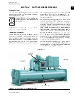
FIGURE 1 

- Front View Of Assembled Unit ..............................................................................................................7

FIGURE 2 

- Form 7 Shipment ..................................................................................................................................8

FIGURE 3 

- Long Term Storage - Tube Side ..........................................................................................................10

FIGURE 4 

- Rigging –  Compressor/Motor Assembly .............................................................................................12

FIGURE 5 

- Variable Speed Drive Rigging .............................................................................................................13

FIGURE 6 

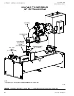
- Form 3 Shipment (Q3-Q7 And P7 Compressors Without Falling Film) ...............................................14

FIGURE 7 

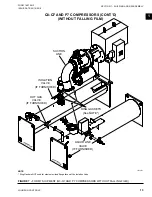
- Form 7 Shipment (Q3-Q7 And P7 Compressors Without Falling Film)) .............................................15

FIGURE 8 

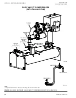
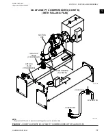
- Form 3 Shipment (Q3-Q7 And P7 Compressors With Falling Film) ....................................................16

FIGURE 9 

- Form 7 Shipment (Q3-Q7 And P7 Compressors With Falling Film) ....................................................17

FIGURE 10 

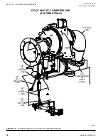
- System Piping (Q3-Q7 And P7 Compressors) ..................................................................................18

FIGURE 11 

- Form 3 Shipment (K Compressors) ..................................................................................................19

FIGURE 12 

- Form 7 Shipment (K Compressors) ..................................................................................................20

FIGURE 13 

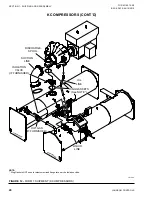
- System Piping (K Compressors) .......................................................................................................21

FIGURE 14 

- Form 3 Shipment (P8-P9 And H9 Compressors Without Falling Film) .............................................22

FIGURE 15 

- Form 7 Shipment (P8-P9 And H9 Compressors Without Falling Film) .............................................23

FIGURE 16 

- Form 3 Shipment (P8-P9 And H9 Compressors With Falling Film) ..................................................24

FIGURE 17 

- Form 7 Shipment (P8-P9 And H9 Compressors With Falling Film) ..................................................25

FIGURE 18 

- System Piping (P8-P9 And H9 Compressors) ..................................................................................26

Summary of Contents for YK

Page 1: ...ERS STYLE G R 134a OR R 513A COOLING ONLY WITH GRAPHIC CONTROL CENTER FOR ELECTROMECHANICAL STARTER SOLID STATE STARTER AND VARIABLE SPEED DRIVE CENTRIFUGAL LIQUID CHILLERS INSTALLATION INSTRUCTIONS S...

Page 2: ...this document and any referenced materials This in dividual shall also be familiar with and comply with all applicable industry and governmental standards and regulations pertaining to the task in que...

Page 3: ...unted MV SSS Manufactured Before 2007 160 00 O5 Operation Floor Mounted MV SSS Manufactured After 2007 160 00 O5 1 Operation Unit Mounted MV SSS 160 00 O7 Operation MV VSD 2300 VAC 6600 VAC 160 00 O6...

Page 4: ...04 15 2019 NOMENCLATURE YK KC K4 H9 CY G MOTOR CODE POWER SUPPLY for 60 Hz 5 for 50 Hz COMPRESSOR CODE CONDENSER CODE EVAPORATOR CODE MODEL STYLE Design Level Refer to YK Engineering Guide Form 160 75...

Page 5: ...amage Shortage 8 Data Plates 9 Long Term Storage 9 Reassembly 11 Q3 Q7 and P7 Compressors Without Falling Film 14 Q3 Q7 and P7 Compressors with Falling Film 16 Q3 Q7 and P7 Compressors System Piping 1...

Page 6: ...3 Q7 And P7 Compressors With Falling Film 16 FIGURE 9 Form 7 Shipment Q3 Q7 And P7 Compressors With Falling Film 17 FIGURE 10 System Piping Q3 Q7 And P7 Compressors 18 FIGURE 11 Form 3 Shipment K Comp...

Page 7: ...with dry ni trogen 2 to 3 PSIG The shipment may include miscellaneous packaging of the control center oil eductor filter tubing water temperature controls wiring oil isolators solid state starter or v...

Page 8: ...2 psig to 3 psig Miscellaneous packaging of tubing water temperature controls wiring isolators etc The unit is shipped with a nitrogen charge The refrigerant charge is shipped in appropriate cylinder...

Page 9: ...f material under pres sure and to protect themselves 1 Check that the working space is open and has good ventilation If is does not have good ventila tion connect a hose or pipe to the valve Item 5 an...

Page 10: ...5 6 7 Nozzle without flanges Lines 4 in through 12 in Nozzle without flanges Lines 14 in through 24 in 8 9 8 9 ITEM DESCRIPTION 1 Tag Warning Dennison 8E 2 Gauge Press 2 Dia 0 30 3 Tag GlvSt Wire Spee...

Page 11: ...onnection Check the transverse alignment by placing a level on the tops of both end sheets Refer to the Installation Unit Form 160 75 N1 for additional instructions to level the unit After shell is le...

Page 12: ...placing a level on the tops of both end sheets refer to Installation Unit Form 160 75 N1 for additional instructions to level the unit After shell is leveled wedge and shim each corner of the shell t...

Page 13: ...unted MV SSS Form 160 75 PW2 7 Reconnect all unit wiring and harnesses refer to Wiring Diagrams Field Connections Remote Mounted MV SSS Form 160 75 PW2 8 Pressure test the unit Relief valves must be p...

Page 14: ...Q7 AND P7 COMPRESSORS WITHOUT FALLING FILM LD13170 SUCTION LINE DISCHARGE LINE DISCHARGE ISOLATION VALVE IF FURNISHED HOT GAS VALVE IF FURNISHED RING GASKETS See NOTE CONDENSER EVAPORATOR Q3 Q7 AND P...

Page 15: ...Q3 Q7 AND P7 COMPRESSORS WITHOUT FALLING FILM CONDENSER EVAPORATOR SUCTION LINE ISOLATION VALVE IF FURNISHED HOT GAS VALVE IF FURNISHED LIQUID LINE VALVE IF FURNISHED RING GASKETS See NOTE Q3 Q7 AND...

Page 16: ...ON VALVE IF FURNISHED HOT GAS VALVE IF FURNISHED RING GASKETS See NOTE CONDENSER EVAPORATOR LD13171b CONDENSER EVAPORATOR LIQUID LINE LD13170a Figure 8 FORM 3 SHIPMENT Q3 Q7 AND P7 COMPRESSORS WITH FA...

Page 17: ...NISHED HOT GAS VALVE IF FURNISHED RING GASKETS See NOTE CONDENSER EVAPORATOR LD13171b Figure 9 FORM 7 SHIPMENT Q3 Q7 AND P7 COMPRESSORS WITH FALLING FILM Q3 Q7 AND P7 COMPRESSORS CONT D WITH FALLING F...

Page 18: ...19 Section 1 Shipping and Reassembly LD13174 Figure 10 SYSTEM PIPING Q3 Q7 AND P7 COMPRESSORS Q3 Q7 AND P7 COMPRESSORS SYSTEM PIPING SUCTION LINE 3 8 OIL RETURN LINE 3 8 OIL RETURN LINE 3 8 COMPRESSOR...

Page 19: ...FORM 3 SHIPMENT K COMPRESSORS LD13172 Ring Gaskets See NOTE DISCHARGE SPOOL ISOLATION VALVE IF FURNISHED SUCTION LINE HOT GAS VALVE IF FURNISHED OIL LINE OIL PUMP PANEL CONTROL PANEL CONDENSER EVAPOR...

Page 20: ...gure 12 FORM 7 SHIPMENT K COMPRESSORS LD13173 CONDENSER EVAPORATOR HOT GAS IF FURNISHED LIQUID LINE OIL LINE RING GASKETS See NOTE DISCHARGE SPOOL SUCTION LINE ISOLATION VALVE IF FURNISHED K COMPRESSO...

Page 21: ...ng and Reassembly FORM 160 75 N3 ISSUE DATE 04 15 2019 1 LD13175 Figure 13 SYSTEM PIPING K COMPRESSORS K COMPRESSORS CONT D 3 4 OIL SUPPLY LINE 1 OIL SUMP VENT LINE 3 8 LIQUID INJECTION LINE 1 REFRIGE...

Page 22: ...P9 AND H9 COMPRESSORS WITHOUT FALLING FILM SUCTION LINE DISCHARGE SPOOL ISOLATION VALVE IF FURNISHED HOT GAS VALVE IF FURNISHED OIL PUMP PANEL CONTROL PANEL CONDENSER EVAPORATOR RING GASKETS See NOTE...

Page 23: ...WITHOUT FALLING FILM SUCTION LINE DISCHARGE SPOOL DISCHARGE ISOLATION VALVE IF FURNISHED HOT GAS VALVE IF FURNISHED LIQUID LINE VALVE CONTROL PANEL OIL PUMP CONTROL PANEL RING GASKETS See NOTE CONDEN...

Page 24: ...M P8 P9 AND H9 COMPRESSORS WITH FALLING FILM FROM CONDENSER TO EVAPORATOR LIQUID LINE LIQUID LINE FROM CONDENSER TO EVAPORATOR DISCHARGE SPOOL SUCTION LINE ISOLATION VALVE IF FURNISHED HOT GAS VALVE I...

Page 25: ...ATOR SUCTION LINE DISCHARGE SPOOL DISCHARGE ISOLATION VALVE IF FURNISHED HOT GAS VALVE IF FURNISHED CONTROL PANEL OIL PUMP CONTROL PANEL RING GASKETS See NOTE LD13185b Figure 17 FORM 7 SHIPMENT P8 P9...

Page 26: ...9 Section 1 Shipping and Reassembly P8 P9 AND H9 CCOMPRESSORS SYSTEM PIPING SUCTION LINE 3 8 OIL RETURN LINE 3 8 OIL RETURN LINE 3 8 COMPRESSOR TO VSOP PANEL 3 4 OIL RETURN LINE 3 4 OIL SUPPLY LINE Fi...

Page 27: ...elsius multiply by 5 9 or 0 5556 Example 10 0 F range x 0 5556 5 6 C range Table 1 SI METRIC CONVERSION MEASUREMENT MULTIPLY ENGLISH UNIT BY FACTOR TO OBTAIN METRIC UNIT Capacity Tons Refrigerant Effe...

Page 28: ...Pennsylvania USA 17349 1 800 524 1330 Subject to change without notice Printed in USA Copyright by Johnson Controls 2019 www johnsoncontrols com ALL RIGHTS RESERVED Form 160 75 N3 419 Issue Date Apri...

Reviews: