


JOHNSON CONTROLS
8
FORM 160.75-N3
ISSUE DATE: 04/15/2019
SECTION 1 - SHIPPING AND REASSEMBLY
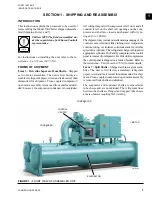
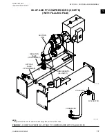
All wiring integral with the compressor is left on. All
wiring harnesses on the shells are removed.
All openings on the compressor and shells are closed
and charged with dry nitrogen (2 psig or 3 psig).
The shipment may include miscellaneous packaging of
control center, oil eductor filter, tubing, water tempera-
ture controls, wiring, oil, isolators, solid state starter, or
variable speed drive (options). The refrigerant charge
is shipped in appropriate cylinders. For P and Q com-
pressors the control panel is removed for shipment. For
H9 and K compressors the control panel is shipped on
a folded bracket. Refer to the
Installation - Unit (Form
160.75-N1)
for more details.
When more than one chiller is involved,
the major parts of each unit are marked
to prevent mixing of assemblies. Piping
and wiring drawings to be furnished by
Johnson Controls.
FORM 9 – Unit Separate from Variable Speed
Drive
Shipped as two major assemblies:
• Chiller Unit
• Variable Speed Drive
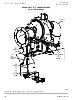
The unit is first factory assembled, refrigerant piped,
wired and leak tested; then dismantled for shipment.
The evaporator/condenser is not skidded.
All wiring integral with the compressor is left on it, and
all conduit is left on shell. All openings on the com-
pressor, and shell are closed and charged with dry ni-
trogen (2 psig to 3 psig).
Miscellaneous packaging of tubing, water temperature
controls, wiring, isolators, etc. The unit is shipped with
a nitrogen charge. The refrigerant charge is shipped in
appropriate cylinders. See
FORM 10 – Unit Separate from Variable Speed
Drive
Shipped as two major assemblies:
• Chiller Unit
• Variable Speed Drive
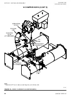
The unit is first factory assembled, refrigerant piped,
wired and leak tested; then dismantled for shipment.
The evaporator/condenser is not skidded.
All wiring integral with compressor is left on it, and all
conduit is left on shell.
Miscellaneous packaging of tubing, water temperature
controls, wiring, isolators, etc. The unit is shipped with
refrigerant charge. See
INSPECTION – DAMAGE – SHORTAGE
Check unit shipment on arrival to see that all major
pieces, boxes, and crates are received. Each unit should
be checked on the trailer or rail car when received, be-
fore unloading, for any visible signs of damage. Report
any damage or signs of possible damage to the trans-
portation company immediately for their inspection.
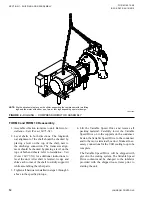
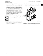
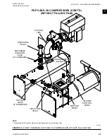
FIGURE 2 -
FORM 7 SHIPMENT
LD03865a
5/8" X 2-1/2" BOLTS,
LOCKWASHERS, AND
HEX NUTS
CONDENSER
EVAPOPATOR
Johnson Controls WILL NOT BE RE-
SPONSIBLE FOR ANY DAMAGE
IN SHIPMENT OR AT JOB SITE OR
LOSS OF PARTS. (Refer to Service
Policy - Shipping Damage Claims, Form
50.15-NM.)
When you receive the containers at the job site, open
and check the contents against the packing list. Report
any material shortage to Johnson Controls immediate-
ly. (Refer to
Service Policy - Shipping Damage Claims,
Form 50.15-NM
.)


