


JOHNSON CONTROLS
12
FORM 160.75-N3
ISSUE DATE: 04/15/2019
SECTION 1 - SHIPPING AND REASSEMBLY
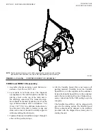
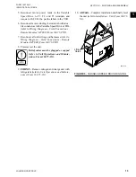
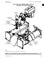
FIGURE 4 -
RIGGING – COMPRESSOR/MOTOR ASSEMBLY
LD02140a
NOTE:
Rig the driveline into place on the chiller, supporting the compressor with two lifting
lugs and the motor with either, one, two, or four legs depending on motor design.
FORM 9 and FORM 10 Reassembly
1. Assemble vibration isolators to unit. Refer to
In-
stallation - Unit (Form 160.75-N1)
.
2. Level shells in both directions. The longitudi-
nal alignment of the shell should be checked by
placing a level on the top of the shell, next to
the discharge connection. The transverse align-
ment should be checked by placing a level on the
tops of both end sheets; refer to
Installation - Unit
(Form 160.75-N1)
for additional instructions to
level the unit. After shell is leveled, wedge and
shim each corner of the shell to solidly support it
while assembling the other parts.
3.
Tighten all hardware installed in steps 3 through 6
above to the specified torque.
4. Lift the Variable Speed Drive and remove all
packing material. Carefully lower the Variable
Speed Drive on to the supports on the condenser.
Fasten the Variable Speed Drive to the condenser
and to the motor terminal box duct. Make all nec-
essary connections for the VSD cooling loop to be
complete.
The Variable Speed Drive will be shipped with
glycol in the cooling system. The Variable Speed
Drive coolant must be changed to the inhibitor
provided with the shipped loose items prior to
starting the unit.


