82
YORK INTERNATIONAL
LD02100
Installation Limitations
The following limitations must be adhered to. Failure to
do so may result in improper printer and/or chiller op-
eration.
1. The printer option is adaptable to all versions and
revisions of microprocessor boards and EPROMs.
No modifications are necessary to the panel.
2. Maximum cable length between the printer and the
microprocessor board is 25 feet. Twisted pair shielded
cable is required.
3. The printer must be supplied a 115VAC source.
4. The printer may be left connected to the micro panel.
Parts
The following parts are required:
1. Weigh-Tronix IMP-24, Model 2600 printer.
2. 2.25" wide desk top calculator paper.
3. 25 ft. Twisted Pair Shielded Cable (minimum 3 con-
ductor), #18 AWG Stranded, 300V min. insulation.
4. (1 ea.) 25-pin Cannon connector and shell. Connec-
tor: Cannon P/N DB-25P or equivalent. Shell: Can-
non P/N DB-C2-J9.
Assembly and Wiring
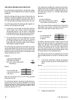
All components should be assembled and wired as fol-
lows in Fig. 34. Strip the outside insulation back several
inches and individual wires about 3/8" to connect the
cable at the Micro Logic Board. Connect the shield of
the cable as shown on the Micro Logic Board. Do not
connect at the printer end of the cable.
Printer Configuration
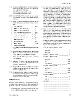
2 Switches on the printer must be properly configured.
Remove the paper roll to access these switches. Place
the switches in the following position:
SW. 1 OFF
SW. 2 ON
Obtaining a Print-out
A print-out of current operating data may be obtained by
pressing the OPER DATA key. A snapshot will be taken
by the micro of current operating conditions. These con-
ditions will be stored in memory until they can be trans-
mitted to the printer and printed. A sample print-out is
shown in Fig. 20 on page 55.
A print-out of the fault shutdown history may be obtained
by pressing the HISTORY key. A print-out showing the
last 3 faults with all system conditions at the time of the
fault will be transmitted. A sample print-out is shown in
Fig. 21 on page 57.
An automatic print-out will be sent to the printer when-
ever the chiller shuts down on a fault, regardless of
whether the fault causes a system or the entire chiller to
lockout or whether restart is permitted. This is the same
print-out that is obtained when the OPER DATA Key is
pressed; however, it will be a snap-shot of system oper-
ating conditions at the instant fault occurred. Additionally,
the Status indication that is noted in the print-out will
note the specific fault that occurred.
Using Other Printers
Control codes vary from printer to printer. This will result
in unusual formatting of printed data from many printers.
In addition, handshaking lines and handshaking se-
quence will differ between printers. This makes the equip-
ment susceptible to operation problems or miswiring
which may cause damage to the printer or the micropro-
cessor board. YORK assumes no responsibility for as-
sistance or damage in the use of non-specified printers.
Warranty
YORK assumes no warranty responsibility in the use of
the printer. This includes damages to the printer and the
microprocessor boards or chiller operation problems
which may result.
FIG. 34
ASSEMBLY AND WIRING


