background image

28

YORK INTERNATIONAL

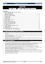
FIG. 22 – DIP SWITCH LOCATION AND POSITION

26001A

LD01098

TOP VIEW

SIDE VIEW

RTC

031-0196-001

DIMPLE
AT TOP

EPROM

TOP

SIDE

“OPEN” POSITION
(LEFT SIDE OF SWITCH IS
PUSHED DOWN)

“CLOSED” POSITION
(RIGHT SIDE OF SWITCH IS
PUSHED DOWN)

S1

DISPLAY/

SWITCH “OPEN” MESSAGE

SWITCH “CLOSED” MESSAGE

SWITCH

1

2

3

4

5

6

7

8

A M B I E N T

&

D I S C H

P R

F A N

C O N T R O L

R 1 3 4 A

D I S C H A R G E

P R E S S U R E

F A N

C O N T R O L

M A N U A L

L E A D

/

L A G

A U T O M A T I C

L E A D

/

L A G

S T A N D A R D

C O N D E N S E R

F A N

C O N T R O L

S H A R E D

C O N D E N S E R

F A N

C O N T R O L

E N G L I S H

U N I T S

R E A D O U T

M E T R I C

U N I T S

R E A D O U T

R E T U R N

W A T E R

C O N T R O L

L E A V I N G

W A T E R

C O N T R O L

L O C A L

C O N T R O L

M O D E

R E M O T E

C O N T R O L

M O D E

S T A N D A R D

A M B I E N T

L O W

A M B I E N T

C O N T R O L

C O M F O R T

C O O L I N G

B R I N E

&

P R O C E S S

D U T Y

TABLE 1 – SWITCH POSITION AND DISPLAY

J19

Summary of Contents for RecipPak YEAZ88DR6

Page 1: ...8 YEAJ65HT8 YEAJ66MT8 50 HZ MODELS YEAJ44DR7 YEAJ55DR7 YEAJ55HT7 YEAJ65ES7 YEAJ66HT9 YEAJ76HT9 YEAJ77MT9 STYLE A With EPROM 031 01096 001 Standard Brine Metric Models Combined 200 230 460 3 60 M A N U...

Page 2: ...ily for central station air conditioning applications with normal installations being on roof tops or on ground level beside the building CODE STATUS The units are designed in accordance with UL 200 2...

Page 3: ...60 28 230 3 60 40 380 3 60 46 460 3 60 50 380 415 3 50 58 575 3 60 64 346 3 50 Motor Manufacturer S A O Smith L Leroy Somer J G 4 3 1 M 17 S COMPRESSOR NOMENCLATURE Compressor Series No of Active Cyl...

Page 4: ...GLASS TX VALVE SIGHT GLASS TXV SYSTEM 1 25212A 26174A UNIT DATA PLATE SIDE OF PANEL MICROPANEL CONDENSER FANS CONDENSER COIL S POWER PANEL COMPRESSOR 2 COMPRESSOR 1 OPTIONALSINGLE POINTPOWERCONNECT CO...

Page 5: ...FORM 150 60 NM4 YORK INTERNATIONAL 5 26068A 26069A FIG 1 UNIT COMPONENTS Cont d INTERIOR VIEW POWER PANEL SINGLEPOINT CONNECTION TERMINALS GROUND LUGS...

Page 6: ...PRESSOR OIL CHARGING VALVE 27294A DISCHARGE STOP VALVE TERMINAL BOX CAPACITY CONTROL SOLENOID OIL PRESURE ACCESSCONN OIL LEVEL SIGHT GLASS CRANKCASE HEATER OIL PUMP DATA PLATE DISCHARGE STOP VALVE CAP...

Page 7: ...ires the Optional Low Ambient kit 3 Operation above 115 F requires Optional High Ambient kit MODEL LVG WATER COOLER4 AIRON YEA TEMP F GPM CONDENSER F MIN 1 MAX MIN MAX MIN 2 MAX 3 Z88DR6 J44DR1 40 50...

Page 8: ...ended and snow accumulations are expected additional unit height must be provided to insure full air flow 2 VIBRATION ISOLATORS optional will increase overall height of unit by approx 6 3 Drawings not...

Page 9: ...4 1140 RPM 60 HZ 3 2 4 3 2 4 3 2 4 3 2 4 5 3 8 5 3 8 5 3 8 HP KW Each 950 RPM 50 HZ 3 2 2 3 2 2 3 2 2 3 2 2 5 4 1 5 4 1 5 4 1 CFM Total 60 HZ 62 200 62 200 60 000 61 100 71 600 71 600 71 600 50 HZ 61...

Page 10: ...1 250MCM J55DR7 64 325 400 450 400 450 1 3 6 350MCM 1 1 600MCM OR 2 1 250MCM J44HT6 17 558 700 700 600 700 1 3 6 350MCM 1 2 4 0 500MCM J44HT6 28 499 600 600 600 600 1 3 6 350MCM 1 2 4 0 500MCM J44HT6...

Page 11: ...1 2 4 250MCM 254 80 4 9 180 225 300 200 450 1 2 4 250MCM 412 134 5 8 180 225 300 200 300 1 2 4 250MCM 412 134 5 8 308 400 500 400 700 1 2 4 250MCM 731 230 10 0 308 400 500 400 500 1 2 4 250MCM 731 23...

Page 12: ...12 YORK INTERNATIONAL DUAL COMPRESSOR POWER SUPPLY WIRING STANDARD UNIT NON FUSED DISCONNECT OPTION SINGLE POINT OPTION LD02072 LD02073 LD02074 See Notes on page 10...

Page 13: ...mage due to rough handling The units are shipped without export crating unless it is specified by Sales Order A unit should be lifted by inserting hooks through the holes provided in unit base rails S...

Page 14: ...27 402237 22 Cu Cu 12 650 13 250 3349 CP 4 28 3045 CP 4 28 3541 CP 4 28 3305 CP 4 28 402237 20 J77MT9 Cu AI 11 650 12 250 3127 CP 4 28 2822 CP 4 27 3261 CP 4 28 3024 CP 4 27 402237 41 Cu Cu 13 000 13...

Page 15: ...Orange 1 06 26 9 CP 4 28 3600 1632 9 Green 1 02 25 9 CP 4 31 4400 1995 8 Gray 83 21 0 CP 4 32 5200 2358 7 White 74 18 7 CP 4 35 6000 2721 6 Gold 70 17 7 COMPRESSOR MOUNTING The compressors are mounte...

Page 16: ...to prevent forma tion of condensation on lines in warm humid climates 7 A chilled water flow switch either by YORK or oth ers MUST be installed in the leaving water piping of the cooler There should...

Page 17: ...C Gold contacts recommended Wiring shall not be run in the same conduit with any line voltage wiring 4 To cycle unit on and off automatically with contact shown install a cycling device in series with...

Page 18: ...t in nui sance faults CAUTION Any inductive devices relay wiredinserieswith the flow switch for start stop into the Alarm cir cuitry or pilot relays for pump starters wired through motor contactor aux...

Page 19: ...FORM 150 60 NM4 YORK INTERNATIONAL 19 FIG 5 SYSTEM WIRING LD02080 LD02082 LD02081 CONNECTION DIAGRAM SYSTEM WIRING YEA 95 160 CONDENSER FANS COOLER COMPRESSORS...

Page 20: ...20 YORK INTERNATIONAL LD02083 COMPRESSOR TERMINAL BOX SYSTEM NO 1 COMPRESSOR TERMINAL BOX SYSTEM NO 2 FIG 6 SYSTEM WIRING Cont d...

Page 21: ...FORM 150 60 NM4 YORK INTERNATIONAL 21 LD02084 CONNECTION DIAGRAM ELECTRICAL BOX YEA 95 160 FIG 7 CONNECTION DIAGRAM...

Page 22: ...22 YORK INTERNATIONAL LD02086 LD02085 LD02087 FIG 7 CONNECTION DIAGRAM Cont d...

Page 23: ...chilled water tempera ture reset can be accomplished by user supplied dry contacts Compressor starting stopping and loading unloading de cisions are performed by the Microprocessor to main tain leavi...

Page 24: ...be at 12VDC potential CURRENT TRANSFORMER C T A C T on the 3 power wiring of each motor sends AC signals proportional to motor current to the Power Sup ply Board which rectifies and filters the signal...

Page 25: ...ONTROL PANEL EXTERIOR MICROPROCESSOR BOARD KEYPAD TB3 26000A LCD DISPLAY BOARD MICROPROCESSOR BOARD UNITON OFF SWITCH 2TTRANSFORMER RELAY OUTPUT BOARD 1 TB3 CONNECTIONS FOR FLOW SWITCH LEAD LAG SELECT...

Page 26: ...ayed If a message is required to be updated faster than every 2 seconds the appropriate key for the desired display may be pushed and held Updating will be at 4 second intervals Each of the keys and a...

Page 27: ...have been selected by the user These options are se lected by the S1 Dip Switch on the Microprocessor Board Fig 12 Proper programming of the switch is important during commissioning of the chiller The...

Page 28: ...R G E P R E S S U R E F A N C O N T R O L M A N U A L L E A D L A G A U T O M A T I C L E A D L A G S T A N D A R D C O N D E N S E R F A N C O N T R O L S H A R E D C O N D E N S E R F A N C O N T R...

Page 29: ...5 F CLOSED The low ambient cut out is programmable from 0 50 F A low ambient kit MUST be installed if the switch is placed in this position SWITCH 3 OPEN DO NOT USE this mode at present CLOSED This sh...

Page 30: ...s mode maximum chiller efficiency will be achieved If the Low Ambient option is installed the fan control will automatically change to pressure control at tempera tures below 25 F See page 68 for fan...

Page 31: ...KEY The DAILY SCHEDULE SHUTDOWN message indicates that the schedule programmed into the CLOCK SET SCHEDULE HOLIDAY is keeping the chiller from run ning Run Permissive is an indicator that an external...

Page 32: ...discharge pres sure has exceeded the user programmable threshold and the micro is unloading the affected system to prevent shutdown on a manual high pressure cut out Reloading will take place when dis...

Page 33: ...R T E M P S Y S 2 H I G H D S C H C H I L L E R F A U L T H I G H A M B I E N T T E M P S Y S 1 L O W O I L P R E S S C H I L L E R F A U L T 1 1 5 V A C U N D E R V O L T A G E S Y S 2 L O W O I L P...

Page 34: ...ough available data after any one of the following keys is pressed PROGRAM SET SCHEDULE HOLIDAY OPER DATA HISTORY Cancel Key The CANCEL key allows the user to change errors in the data being programme...

Page 35: ...CHECKED AND PROPERLY PRO GRAMMED WHEN COMMISSIONING THE CHILLER FAILURE TO PROPERLY PROGRAM THESE VALUES MAY CAUSE DAMAGE TO THE CHILLER OR OPERA TION PROBLEMS DISCHARGE CUT OUT The DISCHARGE CUT OUT...

Page 36: ...r this cut out if S1 Dip Switch 2 on the Micro Logic Board is in the CLOSED position In the OPEN position afixed 25 F cut out is recognized OUTSIDE AIR TMP HIGH CUT OUT The OUTSIDE AIR TMP HIGH CUT OU...

Page 37: ...or reduced loader and compressor cycling Typically this value should be programmed for 00 1 F When programming values like 00 1 F it is first required to key in 00 Example 00 1 F Additional details f...

Page 38: ...ional N A N A N A N A N A N A N A 50HZ J44DR7 J55DR7 J55HT7 J65ES7 J66HT9 J76HT9 J77MT9 Standard 5 Steps 5 Steps 5 Steps 5 Steps 5 Steps 5 Steps 5 Steps Optional N A N A N A N A 7 Steps 7 Steps 7 Step...

Page 39: ...d date will be dis played when the SET TIME key is pressed CLOCK KEYS PROGRAMMING THE SYSTEM CLOCK AND DAILY START STOP SCHEDULE To program the day time and date first press the AD VANCE DAY key until...

Page 40: ...ONDAY that the ENTER KEY is not pressed changing times programmed for the rest of the week If the chiller is not cycled by the DAILY SCHEDULE but is required to run whenever the system switches are on...

Page 41: ...ignored and the chiller will start up when water temperature allows unit switch permits and system switches permit Normally this key is not used unless an emergency forces the chiller to require oper...

Page 42: ...ccording to the user s application and Switch 4 of Dip Switch S1 on the Micro Board is properly configured to select Return or Leaving control the chilled liquid set points can then be programmed into...

Page 43: ...ess the CHILLED LIQUID TEMP RANGE key The display will first exhibit a message that RETURN WATER TEMP CONTROL is selected and 3 seconds later automat ically scroll to the next display of LWT and CR Th...

Page 44: ...mpt to load the chiller as fast as it can 30 sec onds per stage unless the chiller has not run for 3 min utes This allows the chiller to gain control of the water temperature as quickly as possible wh...

Page 45: ...value will be entered into memory and the display will advance to the next user programmable limit The micro will accept a range of programmable values between 0 5 5 0 F min PROGRAMMING LEAVING WATER...

Page 46: ...ram the anti recycle timer for a minimum of 300 seconds if it isn t already programmed for 300 seconds NOTE Whenever reprogramming the LWT CR keep in mind that the desired leaving water temp or target...

Page 47: ...ABOVE THE RATE CONTROL TEMPRANGE RATECONTROLTEMPRANGE RATE CONTROL TEMP 10 F CONTROLRANGE CR 44 46 F BELOWTHE CONTROLRANGE 56 46 45 44 or possibly initiate unloading if temperature drops faster than 2...

Page 48: ...lues between 0 5 5 0 F min LOADING AND UNLOADING RETURN WATER TEMPERATURE CONTROL In return water temperature control loading and unload ing will take place according to the deference between the leav...

Page 49: ...may appear delayed time between stages increased when miss ing steps are activated or deactivated by the micro NOTES 1 The Lead Comp 2 Steps Lag Comp Off Step is skipped on a temperature drop 2 The m...

Page 50: ...MPERATURE ABOVE THE RATE CONTROL RANGE RATECONTROLTEMPRANGE CONTROL RANGE CR BELOW THE CONTROL RANGE If leaving water temperature should fall into the tem perature range BELOW THE CONTROL RANGE which...

Page 51: ...FORM 150 60 NM4 YORK INTERNATIONAL 51 FIG 18 LEAVING WATER CONTROL LOADING UNLOADING 5 STEP FIG 19 LEAVING WATER CONTROL LOADING UNLOADING 7 STEP...

Page 52: ...motor current is exceeding 120 FLA at the 3 second point the compressor will shut down After 4 seconds of operation motor current must be greater than 15 FLA but less than 115 FLA as long as the comp...

Page 53: ...motor stator These sensors are wired into the motor protector module located inside the Motor terminal box As the motor windings heat and cool the resistance of the mo tor temperature sensors will cha...

Page 54: ...below High Ambient Temperature Safety The High Ambient Temperature Safety assures that the chiller does not run in ambients above 130 F where po tential malfunction of system mechanical and electrica...

Page 55: ...he chance of tripping the relief valve due to a very high rate of rise in pressure resulting from a controls problem which would cause condenser water flow to be interrupted In this case the pressure...

Page 56: ...rom memory A sample printout is shown in Fig 20 History The HISTORY key allows the operator to remotely ob tain a printout of information relating to the last 3 Safety YORK INTERNATIONAL CORPORATION R...

Page 57: ...OFF RUNPERMISSIVE ON STAGESOFLOADING 1 FORWARDFANS 2 REVERSEFANS OFF HOTGASBYPASSVALVE OFF SYSTEM2DATA COMPRESSORSTATUS ON MOTORAMPS 0 FLA SUCTIONPRESSURE 61 PSIG DISCHARGEPRESSURE 80 PSIG OILPRESSUR...

Page 58: ...Gas Solenoid is ON or OFF The micro will activate the Hot Gas signal regardless of whether or not this option is installed The Run Time for SYS 1 since the last start is displayed OFF Sys 2 Liquid Lin...

Page 59: ...ded 10 Lead Compr Loaded Lag Compr Loaded On some STEPS actual Loading will NOT change 7 STAGE STEP 0 Both Compressors OFF 1 Lead Compr Unloaded Lag Compr OFF 2 Lead Compr 1 Stage Loading Lag Compr OF...

Page 60: ...ively pressing the ENTER key will allow the operator to scroll through the information available in the SAFETY SHUTDOWN Buffer In the information that follows a sample message along with an explanatio...

Page 61: ...ion pressure of SYS 1 at the time of the fault This message indicates SYS 1 discharge pressure at the time of the fault This display will be a fixed value unless the Discharge Pressure Readout is inst...

Page 62: ...SYS 2 liquid line solenoid was energized ON or de energized OFF at the time of the fault This message informs the operator if SYS 2 Run Per missive flow switch remote START STOP was in the RUN mode ON...

Page 63: ...ition to function as a warning whenever a fault shutdown occurs on any sys tem or if power is lost to the control panel The dry con tacts are normally open N O and will close when con trol power is ap...

Page 64: ...n the OFF position This is also done to maintain water tem perature as close to setpoint as possible If MANUAL Lead Lag is selected an external dry con tact switch must be wired into the chiller This...

Page 65: ...ated and reprogrammed when the chiller is returned to service NOTE ALL PROGRAMMED VALUES AND STORED DATA OTHER THAN THE INTERNAL CLOCK TlME KEEPlNG WILL BE MAIN TAINED IN MEMORY REGARDLESS OF WHETHER...

Page 66: ...verifying that METRIC UNITS READOUT is programmed Page 27 EMS BAS CONTROLS The microprocessor is capable of REMOTE START STOP REMOTE UNLOADING Pulldown demand limit ing and REMOTE SETPOINT RESET Thes...

Page 67: ...suppressed with a user supplied YORK P N 031 00808 suppressor NOTE Remote Setpoint Reset will not operate when a Remote Control Center Option Kit is connected to the Micro Panel The Remote Control Cen...

Page 68: ...nstalled See page 76 The function of the compressor capacity control system is to automatically adjust the compressor pumping capacity to balance with the cooling load at a pre determined return water...

Page 69: ...not available Cylinders 3 4 have no loading solenoids and are truly permanently loaded FIG 27 Z COMPRESSOR UNLOADING SEQUENCE NOTE 6 cylinder compressors do not connect the loading sole noid wiring o...

Page 70: ...ng power control Must meet NEC and all local codes See Figs 9 11 9 Check for proper size fuses in main and control power circuits 10 Verify that field wiring matches the 3 phase power requirements of...

Page 71: ...compressor will start and a flow of liquid should be noted in the liquid indicator After several min utes of operation the bubbles will disappear and there will be a solid column of liquid when the u...

Page 72: ...only after steady op eration of the chiller has been established the leaving chilled liquid has been pulled down to the required tem perature and the unit is running fully loaded Correct superheat set...

Page 73: ...ead compressor will shut down 6 After 30 seconds of run time the oil pressure of the lead compressor must be a minimum of 20 PSID and the suction pressure must be a minimum of 50 of cut out 7 After 60...

Page 74: ...3 Check the refrigerant circuit for leaks 4 Operating Pressures and Temperatures Check to see that operating pressures and temperatures are within the LIMITATIONS shown in this book ANNUALMAINTENANCE...

Page 75: ...01 This kit is not re quired if a second Relay Output Board is already installed NOTE Any inductive devices contactor relay coil con nected to these contacts must be suppressed with YORK P N 031 00808...

Page 76: ...eld Mounted Pump Control Kit is 471 01232 101 This kit is not re quired if a second Relay Output Board is already installed NOTE Any inductive devices contactor relay coil con nected to these contacts...

Page 77: ...SURE FAN CONTROL fan control by discharge pressure only This is selected by placing SW 8 on the microprocessor to the appropriate position See page 30 SW 2 on the microprocessor board must also be pro...

Page 78: ...ther system reaches 320 PSIG fan 1 SYS 1 7M or fan 3 SYS 2 10M will be energized in the reverse direction This fan will remain energized until discharge pressure of either system drops below 120 PSIG...

Page 79: ...ressor off Details for setting the pressure regulator follow RWT Control Hot Gas Operation The hot gas solenoid is energized if the compressor is on its minimum stage of loading and the return water t...

Page 80: ...n pressure faults due to unusual operating condi tions or chiller location problems Fan cycling by discharge pressure only allows higher discharge pressures which in turn raises suction pressure by pe...

Page 81: ...Ca 95402 Phone 1 800 358 9110 or 1 707 527 5555 International Orders Only NOTE The print out is made to be universal to all types of chillers both air and water cooled with or with out options Items...

Page 82: ...y pressing the OPER DATA key A snapshot will be taken by the micro of current operating conditions These con ditions will be stored in memory until they can be trans mitted to the printer and printed...

Page 83: ...should be unnecessary to drill holes 3 Install grilles using the proper hardware and sup ports Refer to Fig 36 and the Parts List for place ment of the grilles and the proper hardware required 4 Notc...

Page 84: ...les to attach the louvered panels where necessary 4 Notch grilles to suit water connection and wiring har nesses as needed 5 If the High Ambient Sunshield Kit or Disconnect Op tion is installed field...

Page 85: ...ed metal parts to prevent rust FIG 38 COMPLETE INSTALLATION Typical Installation Shown 25246A ASSEMBLY INSTRUCTIONS 1 Condensing and remote DX evaporator arrangement shown 2 Standard units with cooler...

Page 86: ...10VDC applied The 0 10VDC signal should be connected to the and terminals on the TB3 Terminal Block at the right of the microprocessor board Be sure polarity is correct CAUTION THE 0 10VDC INPUT SIGN...

Page 87: ...may not Energize be up 2 External motor protector tripped 2 Check for defective External motor protector wiring and motor problems Assure that motor protector is not tripped due to external high press...

Page 88: ...external H P correctly set restart unit Cut out Switch opens 6 Assure OAT sensor is reading properly 6 Place a thermometer next to the sensor a Motor Current Fault and compare reading to the display...

Page 89: ...ter located in 33 0 F 2 09 waterpiping 36 0 F 2 22 38 0 F 2 28 41 0 F 2 37 43 0 F 2 43 46 0 F 2 54 48 0 F 2 60 50 0 F 2 67 53 0 F 2 77 55 0 F 2 83 57 0 F 2 89 59 0 F 2 95 61 0 F 3 02 63 0 F 3 08 65 0...

Page 90: ...d not great enough 3 OK Become familiar with control operation 4 Defective loading solenoid 4 Replace compressor loading solenoid 5 Faulty wiring to loading solenoid 5 Check wiring 6 Defective water t...

Page 91: ...FORM 150 60 NM4 YORK INTERNATIONAL 91...

Page 92: ...98 U S Olympic Team 36USC380 P O Box 1592 York Pennsylvania USA 17405 1592 Subject to change without notice Printed in USA Copyright by York International Corporation 1997 ALL RIGHTS RESERVED Form 150...

Reviews: