


52
YORK INTERNATIONAL
53
YORK INTERNATIONAL
FORM 201.19-EG4
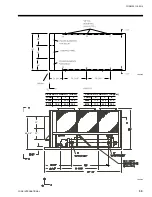
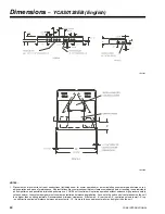
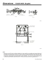
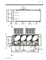
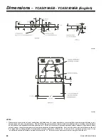
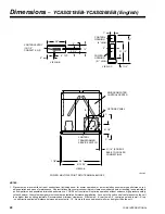
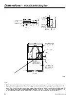
Dimensions
–
YCAS0308EB (English)
LD06121
21 1/4"
91 13/16"
88"
1 7/8"
B
C
C
B
42"
31 1/2"
2"
7"
7 1/2"
(12) 1/2"
12"
28"
2" TYP.
9"
2"
4 3/4"
4 5/16" (EDGE OF
CONNECTION)
BASE TO COOLER
VIEW A-A
OPTIONS PANEL
CONTROL CENTER
MICROCOMPUTER
OPENING
(9" HIGH)
OPENING
(21" HIGH)
CONTROL
POWER
VIEW C-C
CONTROL ENTRY
CONDUIT K.O.'S
VIEW B-B
TRANSFORMER
CONTROL
SERVICE SWITCH
POWER: MULTIPLE POINT WITH TERMINAL BLOCKS
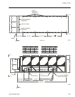
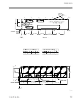
NOTES:
1. Placement on a level surface free of obstructions (including snow, for winter operation) or air recirculation ensures rated performance, reli-
able operation and ease of maintenance. Site restrictions may compromise minimum clearances indicated below, resulting in unpredictable
air flow patterns and possible diminished performance. YORK's unit controls will optimize operation without nuisance high pressure safety
cutout; however, the system designer must consider potential performance degradation. Access to the unit control center assumes the unit
is no higher than on spring isolators. Recommended minimum clearances: Side to wall - 6'; rear to wall - 6'; control panel end to wall - 4'; top
- no obstructions allowed; distance between adjacent units - 10'. No more than one adjacent wall may be higher than the unit.
Summary of Contents for R-407C Optimized
Page 91: ...91 YORK INTERNATIONAL FORM 201 19 EG4 This page intentionally left blank...
Page 110: ...110 YORK INTERNATIONAL Typical Control Wiring 2 Compressor...
Page 118: ...118 YORK INTERNATIONAL This page intentionally left blank...
Page 119: ...119 YORK INTERNATIONAL FORM 201 19 EG4 This page intentionally left blank...