114
YORK INTERNATIONAL
115
YORK INTERNATIONAL
FORM 201.19-EG4
Guide Specifications
(Continued)
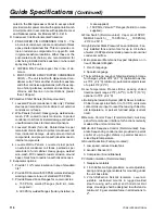
2.03 REFRIGERANT CIRCUIT COMPONENTS
Each independent refrigerant circuit shall include: liquid
line shutoff valve with charging port, low side pressure
relief device, removable core filter-drier, solenoid valve,
sight glass with moisture indicator, expansion valves,
and flexible, closed-cell foam insulated suction line.
2.04 HEAT EXCHANGERS
A. Evaporator:
1. Direct expansion type with refrigerant inside high
efficiency copper tubes, chilled liquid forced over
the tubes by galvanized steel baffles. Independent
refrigerant circuits per compressor.
2. Constructed, tested, and stamped in accordance
with applicable sections of ASME pressure vessel
code for minimum 350 PSIG (24 Bar) refrigerant
side design working pressure and 150 PSIG (10
Bar) water side design working pressure.
3. Shell covered with 3/4" (19 mm), flexible, closed-
cell insulation, thermal conductivity of 0.26k
([BTU/HR-Ft
2
-°F]/in.) maximum. Water nozzles
with grooves for mechanical couplings, and insu-
lated by Contractor after pipe installation.
4. Provide vent and drain fittings, and thermostatically
controlled heaters to protect to -20°F (-29°C) am-
bient in off-cycle.
B. Air Cooled Condenser:
1. Coils: Internally enhanced, seamless copper tubes,
mechanically expanded into aluminum alloy fins
with full height collars. Subcooling coil an integral
part of condenser. Design working pressure shall
be 450 PSIG (31 Bar).
2. Fans: Shall be dynamically and statically bal-
anced, direct drive, corrosion resistant glass fiber
reinforced composite blades molded into low
noise, full airfoil cross section, providing vertical
air discharge from extended orifices for efficiency
and low sound. Each fan in its own compartment
to prevent cross flow during fan cycling. Guards of
heavy gauge, PVC (polyvinyl chloride) coated or
galvanized steel.
3. Fan Motors: High efficiency, direct drive, 6-pole,3-
phase, insulation class “F,” current protected,
Totally Enclosed Air-Over (TEAO), rigid mounted,
with double sealed, permanently lubricated, ball
bearings.
C. Provide Auxiliary Heat Exchangers to increase overall
unit efficiency: U.L./cU.L. Listed 450 PSIG (31 Bar)
design working pressure.
2.05 CONTROLS
A. General: Automatic start, stop, operating, and pro-
tection sequences across the range of scheduled
conditions and transients.
B. Control Circuit Transformer: Factory mounted with
primary breaker having lockable, external handle, and
115V/1Ø secondary.
C. Microprocessor Enclosure: Rain and dust tight
NEMA 3R/12 (IP55) powder painted steel cabinet
with hinged, latched, and gasket sealed door.
D. Microprocessor Control Center:
1. Automatic control of compressor start/stop and
load/unload, anti-coincidence and anti-recycle
timers, automatic pump-down at start-up and
shut-down, condenser fans, evaporator pump,
evaporator heater, unit alarm contacts, run signal
contacts, and chiller operation from 0°F to 125°F
(-18°C to 52°) ambient. Automatic reset to normal
chiller operation after power failure.
2. Setpoint Reset:
a. Pulse Width Modulated (PWM) input to reset cur-
rent unload setpoint downward via signal from
external Energy Management System (EMS),
maximum allowable reset programmable from
microprocessor keypad.
b. PWM input to reset the chilled liquid setpoint
upward via signal from remote EMS, maximum
allowable reset programmable from micropro-
cessor keypad.
3. Software stored in non-volatile memory, with
programmed setpoints retained in lithium battery
backed real time clock (RTC) memory for minimum
5 years.
4. Forty character liquid crystal display, descriptions
in English (or Spanish or French), numeric data in
English (or Metric) units. Sealed keypad with sec-
tions for Setpoints, Display, Entry, Print, Program,
Clock, and Unit On/Off Switch.
5. Programmable Setpoints (within Manufacturer
limits): display language; discharge pressure
unload and cutout; low suction pressure cutout;
low and high ambient cutouts; leaving chilled liquid
temperature: setpoint, control range, and cutout;
high motor current unload; anti-recycle time; lag
compressor start; local or remote control; units of
measure; compressor lead/lag; power failure restart
(auto or manual), and maximum EMS-PWM reset
temperature range.
6. Display Data: Chiller liquid return and leaving tem-
peratures, ambient, lead compressor identification
and lead/lag delay, clock and schedule, (variable)
Summary of Contents for R-407C Optimized
Page 91: ...91 YORK INTERNATIONAL FORM 201 19 EG4 This page intentionally left blank...
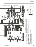
Page 110: ...110 YORK INTERNATIONAL Typical Control Wiring 2 Compressor...
Page 118: ...118 YORK INTERNATIONAL This page intentionally left blank...
Page 119: ...119 YORK INTERNATIONAL FORM 201 19 EG4 This page intentionally left blank...


