YORK INTERNATIONAL
6
ELECTRICAL DATA (Continued)
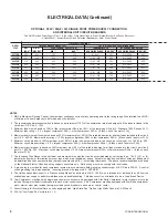
NOTES
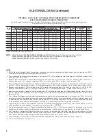
1. MRC is Maximum Running Current, the maximum continuous current at any operating point in the rating range. Also referred to as MCA,
or Minimum Current Ampacity to be furnished by the installer.
2. The recommended disconnect switch is based on a minimum of 115% of the summation rated load amps of all the loads included in the
circuit, per N.E.C. 440 - 12A1.
3. Minimum fuse size is based on 150% of the largest motor RLA plus 100% of the remaining RLAs (U.L. Standard 1995, Section 36.1).
Minimum fuse rating = (1.5 x largest compressor RLA) + other compressor RLAs + (# fans x each fan motor FLA).
4. Maximum dual element fuse size is based on 225% maximum plus 100% of the rated load amps for all other loads included in the circuit,
per N.E.C. 440-22. Maximum fuse rating = (2.25 x largest compressor RLA) + other compressor RLAs + (# fans x each fan motor FLA).
5. Minimum circuit breaker is 150% maximum plus 100% of rated load amps included in the circuit, per circuit per U.L. 1995 Fig. 36.2.
Minimum circuit breaker rating = (1.5 x largest compressor RLA) + other compressor RLAs + (# fans x each fan motor FLA).
6. Maximum circuit breaker is based on 225% maximum plus 100% of the rated load amps for all loads included in the circuit, per circuit,
per U.L. 1995 Fig. 36.2. Maximum circuit breaker rating = (2.25 x largest compressor RLA) + other compressor RLAs + ( # fans x each
fan motor FLA).
7. The Incoming Wire Range is the minimum and maximum wire size that can be accommodated by unit wiring lugs. The (1), (2), or (3)
indicate the number of termination points or lugs which are available per phase. Actual wire size and number of wires per phase must
be determined based on ampacity and job requirements using N.E.C. wire sizing information. The above recommendations are based
on the National Electric Code and using copper connectors only. Field wiring must also comply with local codes.
8. A ground lug is provided for each compressor system to accommodate field grounding conductor per N.E.C. Article 250-54. A control
circuit grounding lug is also supplied. Incoming ground wire range is #6 - 350 MCM.
9. The field supplied disconnect is a Disconnecting Means as defined in N.E.C. 100.B, and is intended for isolating the unit from the
available power supply to perform maintenance and troubleshooting. This disconnect is not intended to be a Load Break Device.
10. Two-Compressor machines with single-point power connection, and equipped with Star-Delta Compressor motor starters, must also
include Factory-provided circuit breakers in each motor control center. 3 & 4 Compressor machine equipped with Star-Delta compressor
motor starter, must also include factory-provided circuit breakers in each motor control center.
11. Consult factory for Electrical Data on units equipped with High Static Fan Option. High Static Fans are 3.5 kW each.
12. FLA for Low Noise Fan motors is 4.1 A.
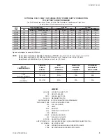
OPTIONAL 380V / 50HZ / 3Ø SINGLE POINT POWER SUPPLY CONNECTION
AND INTERNAL UNIT CIRCUIT BREAKERS
One Field Provided Power Supply Circuit to the chiller. Field connections to Power Terminal Block or Non-Fused Disconnect
in Option Panel. Internal Branch Circuit Protection (Breakers) per Motor Control Center
FIELD SUPPLIED WIRING
MODEL
FIELD PROVIDED POWER SUPPLY
FACTORY PROVIDED (LUGS) WIRE RANGE
YCAS
MRC
MIN NF
OVER-CURRENT PROTECTION
13
TERMINAL BLOCK
NF SERVICE DISC. SWITCH
(MCA
1)
DISC SW
2
MIN.
3, 5
MAX.
4, 6
(LUGS) WIRE RANGE
7
RATING
2
(LUGS) WIRE RANGE
7
RATING
2
0373SB
296
400
300
350
# 1 - 500
380
(2) 3/0-250
400
0403SB
321
400
350
400
(2) # 2 - 300
550
(2) 3/0-250
400
0453SB
375
400
400
450
(2) # 2 - 300
550
(2) 3/0-250
400
0503SB
430
600
450
500
(2) # 1 - 500
760
(3) 2/0-400
630
0543SB
387
400
400
450
(2) # 2 - 300
550
(2) 3/0-250
400
0573SB
455
600
500
500
(2) # 1 - 500
760
(3) 2/0-400
630
0623SB
493
600
500
600
(2) # 1 - 500
760
(3) 2/0-400
630
0653SB
464
600
500
500
(2) # 1 - 500
760
(3) 2/0-400
630
Summary of Contents for MILLENNIUM YCAS0373
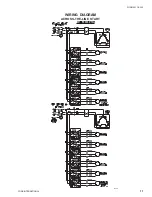
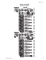
Page 11: ...FORM 201 18 W2 11 YORK INTERNATIONAL LD03228 WIRING DIAGRAM ACROSS THE LINE START...
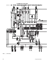
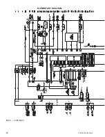
Page 12: ...YORK INTERNATIONAL 12 FIG 1 CONTINUED ELEMENTARY DIAGRAM...
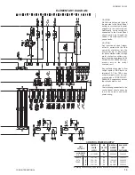
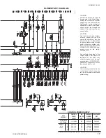
Page 15: ...FORM 201 18 W2 15 YORK INTERNATIONAL WIRING DIAGRAM WYE DELTA START LD03229...
Page 16: ...YORK INTERNATIONAL 16 FIG 2 CONTINUED ELEMENTARY DIAGRAM...
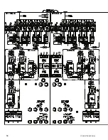
Page 18: ...YORK INTERNATIONAL 18...
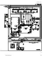
Page 19: ...FORM 201 18 W2 19 YORK INTERNATIONAL LD03280...
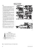
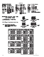
Page 20: ...YORK INTERNATIONAL 20 LEGEND LD03281...
Page 21: ...FORM 201 18 W2 21 YORK INTERNATIONAL LD03282 LD03283 LD03284...
Page 22: ...YORK INTERNATIONAL 22 CONNECTION DIAGRAM SYSTEM WIRING LD03230 LD03231 LD03232...
Page 23: ...FORM 201 18 W2 23 YORK INTERNATIONAL COMPRESSOR TERMINAL BOX LD03233...


