


Prefabricated refrigerant piping is available as an accessory.
If this is not used, piping and insulating materials employed
must be compatible with this type of installation.
Indoor unit gas and liquid line connectors are mounted on
annealed copper tubing stubs and may be shaped to suit the
connection arrangements of your choice. Use the knock-outs
provide in the unit casing. Do not bend stubs to tight angles.
The pre-charged outdoor unit does not require charging if
piping length is 5m or less. However, the interconnecting
piping and the indoor unit must be pumped down before
releasing R22 refrigerant into them from the outdoor unit.
1 - Remove the cap from the service valve.
2 - Connect the line to a vacuum pump and pump down
to 5 Pa.
3 - When pump down is finisned, wait 15 minutes to detect
potential circuit leakage. Open service valves on the
outdoor unit.
* Note
: The expansion device is located in the outdoor unit.
6
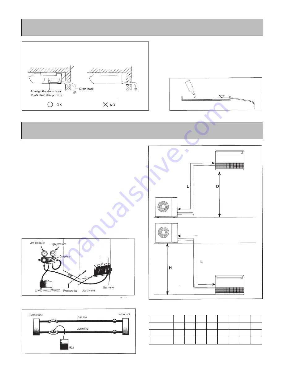
Table 2 - Maximum piping lengths
Note :
Where the difference in elevation is greater than 5 metres,
install an oil trap every 5 metres.
Unit size
D(m)
L(m)
H(m)
7
10
15
12
9
10
15
12
12
12
18
15
18
12
18
15
25
20
25
22
35
20
25
22
45
24
30
26
55
24
30
26
If piping length exceeds 7.5 metres, add 15g of refrigerant
R22 per extra metre.
Install the drain hose.
Be sure to arrange the drain hose so that it is
leveled lower than the drain hose connecting
port of the indoor unit.
Drain tube on unit is flexible and can be routed to
suit various piping arrangements. The drainage
line must include an elbow trap (U bend).
Verification of condensate water drainage :
Fill the drain pan and observe evacuation.
6 - Condensate Drainage
7 - Refrigerant Piping Connections