background image

FORM 160.73-N1 (904)

27

YORK INTERNATIONAL

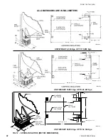
FIG. 16  – 

MOTOR CONNECTIONS (ELECTRO MECHANICAL STARTER APPLICATION)

NOTES:

A.    Requires passing motor lead thru current transformer (CT) once 

before connecting to power supply.

B.    Requires passing motor lead thru CT twice before connecting to 

power supply.

C.  Requires passing motor lead thru CT three times before 

connecting to power supply.

COMPRESSOR MOTOR FIELD CONNECTION DIAGRAM

LD00710


3 PHASE                

MOTOR RATED LOAD AMPS

   MOTOR                                 

CT RATIO

 VOLTAGE


50 / 60 Hz      200:1         350:1          700:1           1400:1

   200-600      65-111

A

     112-224

A

    225-829

A

    830-1790

A

                       11-18

C

2300-4160

    19-37

B

      124-264

A

    265-518

A

                      38-123

A

hav ing a clearance hole for a 3/8" bolt, motor ter mi nal 
lugs are not furnished.

Chiller with Solid State Starter or 
Variable Speed Drive

A chiller equipped with a factory mounted Solid State 
Start er or Vari able Speed Drive does not require wiring 
to the com pres sor motor. The motor power wiring is 
factory con nect ed to the Solid State Starter or Variable 
Speed Drive (or an optional factory in stalled disconnect 
switch). See Field Wiring Diagram. All wiring to the 
control pan el and the oil pump starter is com plet ed by 
the factory. A control trans form er is furnished with the 
Solid State Starter or Vari able Speed Drive.

INSULATION
(SEE PRODUCT DRAWINGS FORM 160.52-PA1)

DO NOT 

fi

  eld insulate until the unit has 

been leak test ed under the su per vi sion 
of  the  YORK  rep re sen ta tive.

Insulation of the type speci

fi

 ed for the job, or minimum 

thick ness to prevent sweat ing of 30°F (-1°C) surfaces 

should be fur nished (by others) and applied to the 
evap o ra tor shell, end sheets, liquid feed line to 

fl

 ow 

cham ber, com pres sor suc tion connection, and evaporator 
liquid heads and con nec tions. The liquid head 

fl

 ange 

in su la tion  must  be  re mov able,  to  allow  head  re mov al  for 
the tube main te nance. De tails of areas to be insulated 
are given on the Product Drawing.

Units are furnished factory anti-sweat insulated on or der 
at additional cost. This includes all low tem per a ture 
sur fac es except the two (2) cooler liquid heads.

INSTALLATION CHECK – 
REQUEST FOR START-UP SERVICE

The services of a YORK representative will be fur nished 
to check the installation and supervise the initial start-
up and operation on all chillers installed within the 
Con ti nen tal  United  States.

After the unit is installed, piped and wired as described 
in this Instruction, but before any attempt is made to start 
the unit, the YORK District Of

fi

 ce should be ad vised so 

that the start-up service, included in the con tract price, 
can be sched uled.  Noti

fi

 cation to the YORK of

fi

 ce 

should be by means of Installation Check List and 
Request, Form 160.49-CL1, in triplicate.

Summary of Contents for MaxE YK

Page 1: ...TM CENTRIFUGAL LIQUID CHILLERS Supersedes 160 73 N1 1102 Form 160 73 N1 904 MODEL YK STYLE F R 134a COOLING ONLY WITH OPTIVIEW CONTROL CENTER FOR ELECTRO MECHANICAL STARTER SOLID STATE STARTER VARIABL...

Page 2: ...CG CH CU CY 5CP 5CU DE DF DG DH DE DF DG DH P8 EK EL EM EK EL EM FK FL FM FK FL FM P8 P9 GJ GK GL GM GJ GK GL GM CH CZ 5CE 5CU HK HL HM HK HL HM EB EB EC ED FB FC FD H5 FB FC FD EB EC ED FB FC FD GB...

Page 3: ...al shall have read and understood this document and any referenced materials This individual shall also be familiar with and comply with all applicable governmental standards and regulations pertainin...

Page 4: ...elief Piping 25 Unit Piping 25 Control Panel Positioning 26 Control Wiring 26 Power Wiring 26 Insulation 27 Installation Check Request for Start up Service 27 LIST OF FIGURES Fig 1 Model YK MaxE Chill...

Page 5: ...FORM 160 73 N1 904 5 YORK INTERNATIONAL FIG 1 MODEL YK MaxE CHILLER 00611VIP OPTIVIEW CONTROL CENTER COMPRESSOR EVAPORATOR MOTOR CONDENSER...

Page 6: ...1 2 10 9 1 2 C 2 0 2 0 2 1 1 4 2 1 1 4 D 1 5 1 2 1 5 1 2 1 8 1 8 E 1 2 7 8 1 2 7 8 1 3 5 8 1 3 5 8 F 12 0 16 0 12 0 16 0 P1 P2 P3 P4 COMPRESSORS EVAPORATOR CONDENSER SHELL CODES A A B B A 5 6 5 6 B 6...

Page 7: ...ELL CODES E E F F G G H H A 2 108 2 108 2 299 2 299 B 3 137 3 137 3 289 3 289 C 610 610 641 641 D 445 445 508 508 E 378 378 397 397 F 3 658 4 877 3 658 4 877 P9 COMPRESSOR EVAPORATOR CONDENSER SHELL C...

Page 8: ...E E F F E F F F G G F G G A 6 6 6 9 6 11 7 2 7 6 7 4 1 2 7 8 1 2 B 8 0 1 4 8 2 3 4 8 0 1 4 8 2 3 4 8 6 3 4 8 2 3 4 8 6 3 4 C 1 9 1 2 1 9 1 2 2 0 2 0 2 0 2 1 1 4 2 1 1 4 D 1 5 1 2 1 7 1 5 1 2 1 7 1 9 1...

Page 9: ...PORATOR H5 COMPRESSORS EVAPORATOR CONDENSER SHELL CODES E E E F F E F F F G G F G G A 1 981 2 057 2 108 2 184 2 286 2 248 2 350 B 2 445 2 508 2 443 2 508 2 305 2 508 2 305 C 546 546 610 610 610 641 64...

Page 10: ...SER SHELL CODES J J T T T V V T V V W V A 9 1 9 1 9 6 9 1 9 6 9 11 B 10 0 3 4 10 0 3 4 10 5 3 4 10 0 3 4 10 5 3 4 10 5 3 4 C 2 5 1 2 2 5 1 2 2 5 1 2 2 5 1 2 2 5 1 2 2 8 D 2 1 2 1 2 3 1 2 2 1 2 3 1 2 2...

Page 11: ...1 7 5 8 1 7 5 8 1 10 1 8 1 7 5 8 K 1 2 2 0 1 4 1 7 5 8 1 7 5 8 1 10 1 8 1 7 5 8 1 PASS CONDENSERS DIM G H J T V X F 1 2 1 9 1 9 3 4 1 9 3 4 1 11 1 8 1 7 5 8 Dimensions Ft In 3 PASS CONDENSERS DIM G H...

Page 12: ...4267 4267 4267 4267 4267 4877 F 603 603 603 603 603 603 603 603 G 375 375 375 375 375 375 375 375 J3 COMPRESSORS EVAPORATOR CONDENSER SHELL CODES H H H J J H A 2502 2604 2667 B 2965 3067 2965 C 667 6...

Page 13: ...H 152 292 311 311 352 299 J 356 464 498 498 562 499 K 356 464 198 498 562 499 1 PASS CONDENSERS DIM G H J T V X F 356 533 552 552 587 499 Dimensions mm 3 PASS CONDENSERS DIM G H J T V X G 356 429 311...

Page 14: ...1 790 F E H5 23 897 29 300 1 900 F F H5 H6 25 396 31 395 2 020 F G H5 H6 27 788 34 635 2 150 G F H3 H5 H6 H7 H8 27 932 34 780 2 290 G G H3 H5 H6 H7 H8 30 315 37 995 2 415 G G J1 J2 29 410 36 850 2 41...

Page 15: ...H5 10 840 13 290 863 F F H5 H6 11 520 14 240 918 F G H5 H6 12 605 15 710 977 G F H3 H5 H6 H7 H8 12 670 15 775 1 040 G G H3 H5 H6 H7 H8 13 750 17 235 1 097 G G J1 J2 13 340 16 715 1 097 G H J1 J2 13 9...

Page 16: ...are shipped dismantled notify the nearest YORK office in ample time for a YORK representative to supervise rigging the unit to its operating position and the assembly of components 4 Do not make fina...

Page 17: ...uld be checked on arrival to see that all major pieces boxes and crates are received Each unit should be checked on the trailer or rail car when received before unloading for any visible signs of dama...

Page 18: ...ove the unit and particularly space provided at either end to permit cleaning or replacement of evaporator and condenser tubes see CLEARANCE A doorway LD00700 R FIG 8 RIGGING or other sufficiently lar...

Page 19: ...EIGHT UP TO 16365 LBS LD08521 UNIT WEIGHT 16 366 TO 28 835 LBS LD08522 LD10114 10 10 10 10 8 3 8 3 2 CONDENSOR CONDENSOR CENTERLINE CENTERLINE END SHEET END SHEET COOLER COOLER CENTERLINE CENTERLINE 3...

Page 20: ...NSOR CONDENSOR CENTERLINE CENTERLINE END SHEET END SHEET COOLER COOLER CENTERLINE CENTERLINE 76 76 SHELLS CENTERLINE SHELLS CENTERLINE END END SHEET SHEET 51 51 FLOOR LAYOUT FLOOR LAYOUT 76 76 A A UNI...

Page 21: ...GHT 35 010 LBS UP TO 58 349 LBS UNIT WEIGHT 10 000 LBS UP TO 35 009 LBS LD03831 LD03830 CONDENSER CENTERLINE SHELL EVAPORATOR CENTERLINE CAP SCREW ADJUSTING BOLT SHELLS CENTERLINE A A 13 8 8 13 ACOUST...

Page 22: ...TO 26 467 Kgs UNIT WEIGHT 4 536 Kgs UP TO 15 880 Kgs LD03834 LD03835 CONDENSER CENTERLINE SHELL EVAPORATOR CENTERLINE CAP SCREW ADJUSTING BOLT SHELLS CENTERLINE A A 343 mm 343 mm 203 mm 203 mm 13 mm 1...

Page 23: ...assemblies will be furnished with the unit The 4 assemblies are identical and can be placed at any of the 4 corners of the unit While the unit is still suspended by the rigging the isolators should b...

Page 24: ...protect the chiller as well as the pumps tower spray nozzles chilled water coils and controls etc The strainer must be installed in the entering chilled water line directly upstream of the chiller Wa...

Page 25: ...nser water heads and piping for leaks Repair leaks as necessary Before initial operation of the unit both water circuits should be thoroughly vented of all air at the high points REFRIGERANT RELIEF PI...

Page 26: ...amperes must be furnished to the control center from the control transformer 2 KVArequired included with the compressor motor starter DO NOT make final power connections to control center until appro...

Page 27: ...r Variable Speed Drive INSULATION SEE PRODUCT DRAWINGS FORM 160 52 PA1 DONOTfieldinsulateuntiltheunithas been leak tested under the supervision of the YORK representative Insulation of the type specif...

Page 28: ...ww york com P O Box 1592 York Pennsylvania USA 17405 1592 Subject to change without notice Printed in USA Copyright by York International Corporation 2004 ALL RIGHTS RESERVED Form 160 73 N1 904 Supers...

Reviews: