FORM 160.73-N1 (904)
25
YORK INTERNATIONAL
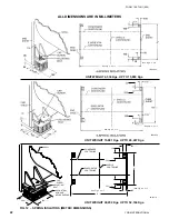
FIG. 14 – TYPICIAL REFRIGERANT VENT PIPING
Stop Valves
Stop valves may be provided (by others) in the
evap o ra tor and condenser water piping adjacent to the
unit to fa cil i tate main te nance. Thermometer wells and
pres sure taps should be provided (by others) in the piping
as close to the unit as pos si ble to facilitate operating
check.
Flow Switches
Thermal type water
fl
ow switches are factory mounted in
the chilled and condensed water nozzles and are factory
wired to the OptiView control panel. These solid-state
fl
ow sensors have a small internal heating element and
use the cooling effect of the
fl
owing
fl
uid to sense when
an adequate
fl
ow rate has been established.
Drain and Vent Valves
Drain and vent valves (by others) should be installed
in the connections provided in the evaporator and
con dens er liquid heads. These connections may be
piped to drain if desired.
Checking Piping Circuits and Venting Air
After the water piping is completed, but before any wa ter
box insulation is applied. Tighten and torque to main tain
between 30 and 60 ft. lbs. (41 and 81 N·m) the nuts on
the liquid head
fl
ang es. Gasket shrinkage and han dling
dur ing tran sit cause nuts to loosen. If water pres sure is
ap plied before tightening is done, the gas kets may be
damaged and have to be replaced. Fill the chilled and
condenser water circuits, operate the pumps man u al ly
and care ful ly check the evaporator and condenser wa ter
heads and piping for leaks. Repair leaks as nec es sary.
Before initial operation of the unit both water circuits
should be thoroughly vented of all air at the high
points.
REFRIGERANT RELIEF PIPING
Each unit is equipped with pressure relief valves lo cat ed
on the condenser and on the evap o ra tor for the pur pose
of quick ly relieving excess pres sure of the re frig er ant
charge to the atmosphere as a safety pre cau tion in case
of an emer gen cy, such as
fi
re.
Refrigerant relief vent piping (by others), from the re lief
valves to the outside of the building, is required by code
in most areas and should be installed on all chill ers. The
vent line should be sized in accordance with the ANSI/
ASHRAE-15, or local code.
The vent line must include
a dirt trap in the vertical leg to intercept and permit clean
out and to trap any vent stack con den sa tion. The piping
MUST be arranged to avoid strain on the relief valves,
using a
fl
exible connection, if nec es sary.
UNIT PIPING
Compressor lubricant piping and system external pip ing
are factory installed on all units shipped as sem bled. On
units shipped dismantled, the following piping should
be com plet ed under the supervision of the YORK
rep re sen ta tive: (1) the lubricant piping to oil sump and
oil evaporator and sys tem oil return connections using
ma te ri al fur nished. See Form 160.73-N3.
FLANGED JOINT
TO PERMIT PIPING
DISASSEMBLY
CONDENSATION
TRAP
DUAL RELIEF
VALVES
VENT TO ATMOSPHERE
SUPPORT VENT PIPING TO AVOID
STRAIN ON RELIEF PIPING
FLEXIBLE CONNECTOR
CONDENSER
COOLER
SEE NOTE
NOTE:
SHELLS MAY BE FURNISHED WITH
ONE
OR
TWO RELIEF VALVES,
DEPENDING ON SHELL SIZE.
LD03863
EVAPORATOR


