JOHNSON CONTROLS
112
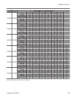
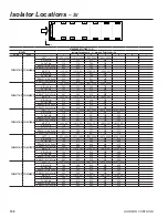
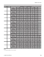
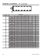
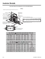
FOR UNITS WITH ALL POINT LOADS LESS THATN 1404 LBS (637 KG)
Weight Range (lbs)
Weight Range (kg)
Model Number
Color
239 to 384 lbs
108 to 174 kg
CIP-B-
Red
384 to 639 lbs
174 to 290 kg
CIP-B-
White
639 to 851 lbs
290 to 386 kg
CIP-B-
Blue
851 to 1064 lbs
386 to 483 kg
CIP-B-
Gray
1064 to 1404 lbs
483 to 637 kg
CIP-B-
Black
FOR UNITS WITH ANY POINT LOAD ABOVE 1404 LBS (637 KG)
Weight Range (lbs)
Weight Range (kg)
Model Number
Color
Up to 851 lbs
Up to 386 kg
CIP-C-
Black
851 to 1149 lbs
386 to 521 kg
CIP-C-
Yellow
1149 to 1489 lbs
521 to 675 kg
CIP-C-
Black
1489 to 1786 lbs
675 to 910 kg
CIP-C-
Yellow w/ Red
1786 to 2028 lbs
910 to 920 kg
CIP-C-
Yellow w/ Green
2028 to 2254 lbs
920 to 1022 kg
CIP-C-
Red w/ Red
2254 to 2936 lbs
1022 to 1332 kg
CIP-C-
Red w/ Green
Isolator Details
CIP-X-
ONE INCH DEFLECTION SPRING ISOLATOR CROSS-REFERENCE
E
Illustration shows single spring CIP-B or CIP-C mount.
HCL
SBC
Slot Width - SW
HCW
MAX BOLT
DIA. - MBD
BASE PLATE DIMENSIONS
NON-SKID NEOPRENE
ACOUSTICAL ISOLATION PAD
(Bolting to floor is not necessary for
indoor applications)
All springs have additional
travel to solid equal to 50%
of the rated deflection.
A
L
FREE &
OPERATING
HEIGHT
T
W
FERROUS HOUSING
SIDE ACCESS INTERNAL
ADJUSTMENT BOLT
Turn clockwise to load
spring and maintain Free
& Operating Height.
Dowel Pin is 3/8" dia. for
CIP-A & 1/2" thereafter
Mounting may be
operated 1/2" above
Free & Operating
Height.
NOTE-
CIP Mounts are not
to be used in seismic
or wind load
applications.
EQUIPMENT BASE
TYPE CIP DIMENSIONS (inches)†
†Casting dimensions may vary ±1/8"
Size
A
L
T
W SW
HCL HCW MBD SBC
Free
Ht.
CIP-B
8
/4
/2
/16
8
CIP-C
6
/8
/16
/8
5
1
1
7
7
3
3
/8
1
6
/4
3
/
5
/4
3
8
/8
7
/16
9
2
/4
3
3
/2
1
/2
/4
1
1
6
7
/2
/4
1
3
1
1
/4
/8
1
7
7
7
Min
Ht.
5
/4
1
6
/4
3
6
Summary of Contents for Latitude YCIV0157E
Page 115: ...JOHNSON CONTROLS FORM 201 23 EG1 1007 115 INTENTIONALLY LEFT BLANK...
Page 127: ...JOHNSON CONTROLS FORM 201 23 EG1 1007 127 INTENTIONALLY LEFT BLANK...
Page 128: ...JOHNSON CONTROLS 128 Typical Control Wiring Two Compressor...
Page 130: ...JOHNSON CONTROLS 130 Typical Control Wiring Three Compressor...
Page 138: ...JOHNSON CONTROLS 138...
Page 139: ...JOHNSON CONTROLS FORM 201 23 EG1 1007 139...
Page 140: ...Form 201 23 EG1 1007 Supersedes 201 23 EG1 607 File in ET2...

