background image

JOHNSON CONTROLS

FORM 201.23-EG1 (1007)

109

MODEL

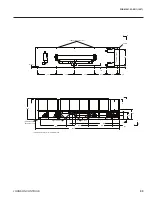
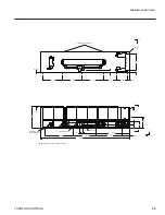
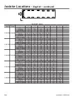
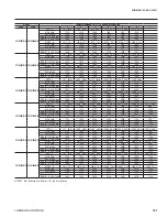
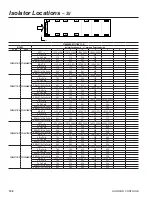
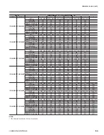
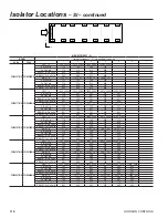
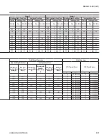
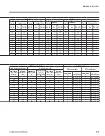
Isolator Locations ( x , y ) - mm and Point Loads - kg

60 Hz

50 Hz

1

2

3

4

5

6

7

YCIV0247S/P YCIV0920S/P

LEFT - L

 ( 230 , 2204 )   ( 1510 , 2204 )   ( 2470 , 2204 )   ( 4100 , 2204 )   ( 5350 , 2204 )   ( 7820 , 2204 ) 

Al Fin Coils

784

743

566

526

572

435

Cu Fin Coils

784

784

675

651

730

544

RS&LS1 / Al Fin Coils

865

824

566

526

572

435

RS&LS1 / Cu Fin Coils

865

865

675

651

730

544

RIGHT - R

 ( 230 , 32 ) 

 ( 1510 , 32 ) 

 ( 2470 , 32 ) 

 ( 4100 , 32 ) 

 ( 5350 , 32 ) 

 ( 7820 , 32 ) 

Al Fin Coils

780

737

562

523

561

433

Cu Fin Coils

780

778

671

648

719

542

RS&LS1 / Al Fin Coils

861

818

562

523

561

433

RS&LS1 / Cu Fin Coils

861

859

671

648

721

542

YCIV0267S/P YCIV1000S/P

LEFT - L

 ( 230 , 2204 )   ( 1510 , 2204 )   ( 2470 , 2204 )   ( 4100 , 2204 )   ( 5350 , 2204 )   ( 7820 , 2204 ) 

Al Fin Coils

784

743

566

526

574

456

Cu Fin Coils

784

784

675

651

732

565

RS&LS1 / Al Fin Coils

865

824

566

526

574

456

RS&LS1 / Cu Fin Coils

865

865

675

651

732

565

RIGHT - R

 ( 230 , 32 ) 

 ( 1510 , 32 ) 

 ( 2470 , 32 ) 

 ( 4100 , 32 ) 

 ( 5350 , 32 ) 

 ( 7820 , 32 ) 

Al Fin Coils

784

743

566

526

574

456

Cu Fin Coils

784

784

675

651

732

565

RS&LS1 / Al Fin Coils

865

824

566

526

574

456

RS&LS1 / Cu Fin Coils

865

865

675

651

734

565

YCIV0287S/P YCIV1070S/P

LEFT - L

 ( 230 , 2204 )   ( 1475 , 2204 )   ( 2823 , 2204 )   ( 5199 , 2204 )   ( 7236 , 2204 )   ( 9346 , 2204 ) 

Al Fin Coils

795

719

826

821

963

533

Cu Fin Coils

805

797

982

978

1119

611

RS&LS1 / Al Fin Coils

875

799

826

821

993

663

RS&LS1 / Cu Fin Coils

855

877

982

978

1149

741

RIGHT - R

 ( 230 , 32 ) 

 ( 1475 , 32 ) 

 ( 2823 , 32 ) 

 ( 5199 , 32 ) 

 ( 7236 , 32 ) 

 ( 9346 , 32 ) 

Al Fin Coils

795

724

1092

1095

1195

535

Cu Fin Coils

805

802

1248

1252

1351

613

RS&LS1 / Al Fin Coils

875

804

1092

1095

1225

665

RS&LS1 / Cu Fin Coils

885

882

1248

1252

1381

743

YCIV0307S/P YCIV1180S/P

LEFT - L

 ( 230 , 2204 )   ( 1475 , 2204 )   ( 2823 , 2204 )   ( 5199 , 2204 )   ( 7236 , 2204 )   ( 9346 , 2204 ) 

Al Fin Coils

795

719

886

897

1045

537

Cu Fin Coils

805

797

1042

1054

1201

615

RS&LS1 / Al Fin Coils

875

799

886

897

1075

667

RS&LS1 / Cu Fin Coils

885

877

1042

1054

1231

745

RIGHT - R

 ( 230 , 32 ) 

 ( 1475 , 32 ) 

 ( 2823 , 32 ) 

 ( 5199 , 32 ) 

 ( 7236 , 32 ) 

 ( 9346 , 32 ) 

Al Fin Coils

795

724

1152

1194

1314

539

Cu Fin Coils

805

802

1308

1351

1470

607

RS&LS1 / Al Fin Coils

875

804

1152

1194

1344

669

RS&LS1 / Cu Fin Coils

885

882

1308

1351

1500

747

YCIV0357S/P YCIV1340S/P

LEFT - L

 ( 230 , 2204 )   ( 1510 , 2204 )   ( 2780 , 2204 )   ( 4710 , 2204 )   ( 7225 , 2204 )   ( 9105 , 2204 )   ( 10463 , 2204 ) 

Al Fin Coils

795

719

886

897

886

517

429

Cu Fin Coils

805

786

1015

1072

1061

646

483

RS&LS1 / Al Fin Coils

875

799

886

897

886

597

509

RS&LS1 / Cu Fin Coils

885

866

1015

1072

1061

726

563

RIGHT - R

 ( 230 , 32 ) 

 ( 1510 , 32 ) 

 ( 2780 , 32 ) 

 ( 4710 , 32 ) 

 ( 7225 , 32 ) 

 ( 9105 , 32 )   ( 10463 , 32 ) 

Al Fin Coils

795

724

1152

1194

1152

522

429

Cu Fin Coils

805

778

1281

1369

1327

651

483

RS&LS1 / Al Fin Coils

875

804

1152

1194

1152

602

509

RS&LS1 / Cu Fin Coils

885

858

1281

1369

1327

731

563

YCIV0397S/P YCIV1500S/P

LEFT - L

 ( 230 , 2204 )   ( 1510 , 2204 )   ( 2780 , 2204 )   ( 4710 , 2204 )   ( 7572 , 2204 )   ( 9530 , 2204 )   ( 11582 , 2204 ) 

Al Fin Coils

801

729

886

897

926

637

479

Cu Fin Coils

811

796

1015

1072

1101

766

533

RS&LS1 / Al Fin Coils

881

809

886

897

926

717

559

RS&LS1 / Cu Fin Coils

891

876

1015

1072

1101

846

613

RIGHT - R

 ( 230 , 32 ) 

 ( 1510 , 32 ) 

 ( 2780 , 32 ) 

 ( 4710 , 32 ) 

 ( 7572 , 32 ) 

 ( 9530 , 32 )   ( 11582 , 32 ) 

Al Fin Coils

801

734

1152

1194

1192

642

479

Cu Fin Coils

811

788

1281

1369

1367

771

533

RS&LS1 / Al Fin Coils

881

814

1152

1194

1192

722

559

RS&LS1 / Cu Fin Coils

891

868

1281

1369

1367

851

613

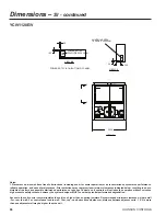
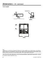
NOTES:

1.  RS = Reduced Sound Option, LS = Low Sound Option

Summary of Contents for Latitude YCIV0157E

Page 1: ...FORM 201 23 EG1 1007 Air Cooled Screw Liquid Chillers 150 385 TONS 527 1354 kWi 2 and 3 Compressor 50 and 60 Hz ASHRAE 90 1 Compliant R134a 140 200 Tons 60Hz...

Page 2: ...y Ratings SI 380V 60Hz 48 High Efficiency Ratings SI 380V 60Hz 52 Physical Data English Standard Efficiency 56 Physical Data English High Efficiency 58 Physical Data SI Standard Efficiency 60 Physical...

Page 3: ...t off design condi tions the chiller sound output is reduced when it is the most sensitive to neighbors evenings and weekends With the introduction of the YCIV model air cooled chiller system designer...

Page 4: ...otor starters In addition by eliminating the heat build up during starting the required off time between starts is reduced to a maximum of two minutes Many utility companies charge an additional fee i...

Page 5: ...yvinyl chloride coated Standard and reduced sound level models have condensers fitted with single speed fans Low sound models have two speed fans fitted The fan motors are the high efficiency direct d...

Page 6: ...chilled liquid temperature under voltage and flow switch operation COMPLETE FACTORY PACKAGE These air cooled chillers are shipped as a complete factory package Each unit is completely assembled with a...

Page 7: ...sound level on demand The SilentNight control option provides a control input to limit sound output of the chiller based on time of day This feature is programmable at the chiller panel or can be cont...

Page 8: ...ree air flow This can cut installation cost by eliminating the need for separate expensive fencing Factory mounted Louvered Panels condenser coils only Painted steel to match unit panels louvered pane...

Page 9: ...JOHNSON CONTROLS FORM 201 23 EG1 1007 NOMENCLATURE The Model Number denotes the following characteristics of the unit Nomenclature...

Page 10: ...V 0157 E V 40 60 160 750 0 125 0650 S P 0177 S P 40 60 160 750 0 125 0630 E V 0177 E V 40 60 160 750 0 125 0720 S P 0187 S P 40 60 160 750 0 125 0700 E V 0187 E V 40 60 160 750 0 125 0760 E V 0197 E...

Page 11: ...177 E V 4 4 15 6 10 1 47 3 17 8 51 7 0720 S P 0187 S P 4 4 15 6 10 1 47 3 17 8 51 7 0700 E V 0187 E V 4 4 15 6 10 1 47 3 17 8 51 7 0760 E V 0197 E V 4 4 15 6 11 4 47 3 17 8 51 7 0770 S P 0207 S P 4 4...

Page 12: ...number YCIV 60Hz 50Hz A 0157 S P 0600 S P B 0157 E V 0590 E V 0177 S P E V 0630 E V 0650 S P 0187 S P E V 0700 E V 0720 S P C 0197 E V 0760 E V 0207 E V 0800 E V 0227 E V 0830 E V D 0207 S P 0770 S P...

Page 13: ...mber YCIV 60Hz 50Hz A 0157 S P 0600 S P B 0157 E V 0590 E V 0177 S P E V 0630 E V 0650 S P 0187 S P E V 0700 E V 0720 S P C 0197 E V 0760 E V 0207 E V 0800 E V 0227 E V 0830 E V D 0207 S P 0770 S P 02...

Page 14: ...P 0287EA VA 1120 E V B 0307SA PA 1180 S P 0327EA VA 1220 E V 0357SA PA 1340 S P 0357EA VA 1380 E V 0397SA PA 1500 S P 1 10 100 100 1000 Water Flow Rate GPM Pressure Drop f t H2 O 2000 A B Pressure Dro...

Page 15: ...FORM 201 23 EG1 1007 15 EVAP YCIV MODELS 60Hz 50Hz A 0267EA VA 1050 E V 0287SA PA 1070 S P 0287EA VA 1120 E V B 0307SA PA 1180 S P 0327EA VA 1220 E V 0357SA PA 1340 S P 0357EA VA 1380 E V 0397SA PA 1...

Page 16: ...206 2 8 7 154 0 215 3 8 1 147 5 222 8 7 5 131 8 207 2 7 2 44 0 176 1 146 8 13 2 174 6 158 3 12 2 172 8 170 6 11 3 170 7 183 5 10 4 168 4 196 8 9 6 163 8 206 8 8 9 158 3 215 8 8 3 151 5 223 4 7 7 133 6...

Page 17: ...270 0 8 3 190 2 277 4 7 8 182 1 284 2 7 3 44 0 224 9 183 7 13 5 222 7 197 3 12 5 220 4 212 0 11 6 218 0 227 7 10 7 215 3 244 2 9 9 211 9 262 1 9 1 203 5 270 1 8 5 195 2 277 6 8 0 186 9 284 5 7 4 45 0...

Page 18: ...6 13 5 282 6 249 6 12 5 279 6 269 2 11 5 276 3 290 0 10 6 272 7 311 7 9 8 266 3 330 6 9 1 257 7 346 2 8 4 246 8 357 8 7 8 214 8 318 9 7 6 45 0 289 6 232 6 13 7 286 9 250 5 12 6 283 9 270 0 11 7 280 6...

Page 19: ...375 7 421 3 10 1 362 4 436 7 9 4 349 2 451 6 8 8 316 5 421 3 8 5 55 0 421 3 312 6 14 9 417 2 333 5 13 9 412 9 355 6 13 0 408 1 379 9 12 0 402 9 405 5 11 2 390 4 422 8 10 4 376 6 437 8 9 7 362 8 452 6...

Page 20: ...4 11 4 166 4 172 9 10 6 164 3 186 0 9 8 160 0 198 0 9 0 154 1 209 1 8 3 147 5 219 9 7 5 48 0 178 0 132 6 14 5 176 7 141 8 13 5 175 1 151 8 12 6 173 4 162 5 11 7 171 5 174 0 10 9 169 1 186 9 10 0 164...

Page 21: ...8 221 1 10 7 210 0 239 2 9 8 204 8 253 1 9 1 197 1 262 0 8 4 189 0 269 7 7 9 48 0 228 1 168 1 14 7 226 1 179 3 13 7 224 0 192 2 12 8 221 7 206 5 11 8 219 2 222 0 10 9 216 2 239 8 10 0 210 6 253 2 9 3...

Page 22: ...9 268 5 11 2 269 5 288 9 10 4 265 6 312 2 9 5 258 9 331 4 8 8 247 9 343 6 8 1 237 1 355 1 7 5 45 0 285 5 216 3 14 3 283 1 232 3 13 3 280 3 249 9 12 3 277 2 269 1 11 4 273 7 289 5 10 5 269 7 312 7 9 6...

Page 23: ...45 0 364 6 10 6 333 5 380 8 9 8 319 9 393 2 9 1 304 6 401 2 8 5 55 0 384 2 270 0 15 5 380 5 284 7 14 7 376 6 302 2 13 7 372 3 322 4 12 8 367 7 344 7 11 9 359 2 365 2 11 0 346 6 380 1 10 2 332 4 392 2...

Page 24: ...7 2 5 510 0 210 8 2 3 480 5 199 1 2 3 9 0 657 2 154 0 3 9 645 6 175 6 3 4 629 2 198 4 3 0 594 0 215 1 2 6 516 0 206 7 2 3 485 4 194 9 2 3 10 0 674 6 155 3 4 0 663 0 176 8 3 5 645 1 198 8 3 0 608 1 215...

Page 25: ...282 0 2 3 679 1 284 4 2 3 9 0 839 7 193 2 4 0 824 0 218 7 3 5 805 9 247 7 3 1 762 0 268 7 2 7 706 0 282 1 2 4 692 1 282 7 2 3 10 0 862 6 195 2 4 1 846 3 220 4 3 6 827 6 249 2 3 1 779 7 268 8 2 7 722...

Page 26: ...1045 3 276 9 3 5 1018 8 313 5 3 0 966 3 344 1 2 6 829 3 324 3 2 4 780 4 306 1 2 4 10 0 1093 8 245 4 4 1 1073 7 278 7 3 6 1045 2 314 4 3 1 989 4 344 2 2 7 838 5 317 7 2 5 787 8 299 7 2 5 11 0 1123 1 24...

Page 27: ...MODEL YCIV0397S P AIR TEMPERATURE ON CONDENSER C LCWT 25 0 30 0 35 0 40 0 45 0 46 0 C KWo KWi COP KWo KWi COP KWo KWi COP KWo KWi COP KWo KWi COP KWo KWi COP 5 0 1343 1 335 5 3 7 1321 0 381 2 3 2 129...

Page 28: ...0 626 1 136 3 4 1 616 5 154 0 3 7 604 7 174 1 3 2 583 5 196 4 2 8 543 5 216 2 2 4 534 8 220 2 2 3 10 0 643 1 137 6 4 2 633 2 155 1 3 7 621 1 175 1 3 3 598 3 197 2 2 8 556 5 216 8 2 4 546 5 219 8 2 3...

Page 29: ...196 4 3 8 793 9 223 0 3 3 765 5 250 6 2 8 712 3 265 9 2 5 701 5 268 7 2 4 11 0 846 0 176 7 4 3 831 6 198 0 3 8 815 1 224 1 3 4 784 3 250 7 2 9 728 9 265 5 2 6 718 0 268 3 2 5 12 0 868 2 179 1 4 4 853...

Page 30: ...6 256 3 3 7 1010 5 291 5 3 2 971 8 328 9 2 8 898 2 351 0 2 4 883 6 355 2 2 3 10 0 1079 0 228 4 4 3 1060 9 258 0 3 8 1038 2 293 0 3 3 995 5 328 8 2 8 920 0 351 1 2 5 905 0 355 3 2 4 11 0 1108 1 231 0...

Page 31: ...DEL YCIV0357E V AIR TEMPERATURE ON CONDENSER C LCWT 25 0 30 0 35 0 40 0 45 0 46 0 C KWo KWi COP KWo KWi COP KWo KWi COP KWo KWi COP KWo KWi COP KWo KWi COP 5 0 1234 1 293 3 3 8 1212 4 332 4 3 3 1186 6...

Page 32: ...4 1 660 4 173 1 3 5 642 6 194 8 3 1 605 9 211 0 2 7 520 5 199 0 2 5 488 9 187 6 2 4 11 0 689 4 153 4 4 1 677 8 174 4 3 6 658 6 195 3 3 2 620 3 211 4 2 8 525 7 194 9 2 5 493 2 183 6 2 5 12 0 707 1 154...

Page 33: ...15 7 3 6 823 6 244 0 3 2 776 3 263 4 2 8 719 2 276 5 2 5 697 1 272 2 2 4 11 0 881 7 193 0 4 2 864 9 217 5 3 7 845 6 245 6 3 2 794 4 263 5 2 8 735 9 276 4 2 5 703 5 266 0 2 5 12 0 905 3 195 2 4 3 888 1...

Page 34: ...8 3 6 1040 2 307 9 3 2 985 0 337 2 2 7 836 6 312 5 2 5 786 4 295 0 2 5 11 0 1117 8 242 5 4 2 1097 2 274 7 3 7 1066 9 308 9 3 2 1008 2 337 3 2 8 845 3 306 1 2 6 793 4 288 8 2 6 12 0 1147 6 245 2 4 3 11...

Page 35: ...Wi COP 5 0 1337 3 328 4 3 7 1315 3 373 1 3 3 1289 8 422 2 2 9 1249 5 473 4 2 5 1187 1 512 7 2 2 1174 5 520 5 2 1 6 0 1374 7 331 0 3 8 1351 8 375 7 3 3 1325 2 424 9 2 9 1280 8 475 2 2 5 1216 1 514 6 2...

Page 36: ...3 630 5 151 8 3 8 618 5 171 4 3 3 596 0 193 1 2 9 554 4 212 3 2 4 545 5 216 2 2 4 11 0 657 7 136 0 4 4 647 5 153 0 3 9 635 1 172 5 3 4 610 9 193 9 2 9 567 6 212 9 2 5 551 5 211 4 2 4 12 0 675 2 137 4...

Page 37: ...192 3 3 8 790 5 218 4 3 3 762 5 245 6 2 9 709 5 260 7 2 5 698 7 263 4 2 5 11 0 842 4 172 9 4 4 828 1 193 8 3 9 811 6 219 5 3 4 781 3 245 8 3 0 726 1 260 3 2 6 715 2 263 0 2 5 12 0 864 5 175 1 4 5 850...

Page 38: ...33 0 286 9 3 3 991 0 322 2 2 9 915 8 344 0 2 5 901 0 348 2 2 4 11 0 1102 8 225 9 4 4 1084 4 254 3 3 9 1061 2 288 3 3 4 1015 0 322 2 2 9 938 0 344 0 2 6 922 6 348 2 2 5 12 0 1132 3 228 7 4 5 1113 6 256...

Page 39: ...5 0 1228 4 287 0 3 9 1206 7 325 4 3 4 1181 0 367 8 3 0 1146 5 415 9 2 6 1083 9 450 5 2 3 1070 4 456 8 2 2 6 0 1263 2 289 6 4 0 1241 1 327 6 3 5 1214 5 370 0 3 0 1177 1 417 5 2 6 1111 7 451 6 2 3 1097...

Page 40: ...179 9 156 3 12 7 178 1 168 3 11 8 175 9 180 9 10 9 173 5 193 9 10 0 168 5 203 2 9 3 162 6 211 9 8 7 155 6 219 5 8 0 135 3 194 7 7 8 48 0 186 9 146 5 14 0 185 4 157 6 13 0 183 5 169 5 12 0 181 3 182 1...

Page 41: ...13 0 227 2 209 4 12 1 224 6 224 7 11 2 221 8 240 9 10 3 217 5 257 0 9 5 208 9 264 8 8 9 200 3 272 2 8 3 191 8 279 0 7 8 48 0 238 9 184 1 14 3 236 7 197 0 13 3 234 2 211 1 12 3 231 4 226 4 11 4 228 5 2...

Page 42: ...4 261 2 339 4 8 7 250 0 351 0 8 0 216 1 309 1 7 8 46 0 294 0 229 0 14 1 291 3 246 4 13 0 288 3 265 4 12 0 284 9 285 7 11 1 280 7 306 3 10 3 274 1 324 8 9 5 264 7 339 5 8 8 253 4 351 2 8 2 217 5 305 6...

Page 43: ...1 9 385 9 392 4 11 0 375 7 412 9 10 3 362 4 427 9 9 6 349 2 442 5 8 9 316 5 412 9 8 6 55 0 421 3 306 4 15 2 417 2 326 8 14 2 412 9 348 5 13 2 408 1 372 3 12 3 402 9 397 4 11 4 390 4 414 3 10 6 376 6 4...

Page 44: ...171 4 137 7 13 5 169 9 147 6 12 5 168 2 158 2 11 7 166 4 169 4 10 8 164 3 182 2 10 0 160 0 194 0 9 2 154 1 204 9 8 4 147 5 215 5 7 7 48 0 178 0 129 9 14 7 176 7 138 9 13 8 175 1 148 7 12 8 173 4 159 2...

Page 45: ...3 7 217 4 187 0 12 7 215 1 201 3 11 7 212 8 216 6 10 9 210 0 234 4 10 0 204 8 248 1 9 2 197 1 256 7 8 6 189 0 264 3 8 0 48 0 228 1 164 7 14 9 226 1 175 7 14 0 224 0 188 3 13 0 221 7 202 3 12 0 219 2 2...

Page 46: ...262 4 324 8 9 0 251 3 336 8 8 4 240 3 348 2 7 8 46 0 289 9 213 1 14 7 287 4 228 5 13 7 284 6 245 7 12 7 281 4 264 4 11 7 277 9 284 3 10 8 273 8 307 1 9 9 266 0 324 8 9 2 254 7 336 9 8 5 243 5 348 4 7...

Page 47: ...MODEL YCIV0357E V E_IPLV 12 4 V_IPLV 15 6 AIR TEMPERATURE ON CONDENSER F LCWT 75 0 80 0 85 0 90 0 95 0 100 0 105 0 110 0 115 0 F TONS KW EER TONS KW EER TONS KW EER TONS KW EER TONS KW EER TONS KW EER...

Page 48: ...2 6 508 8 207 2 2 3 479 4 195 7 2 3 9 0 654 7 150 8 4 0 643 0 171 9 3 5 626 8 194 3 3 0 591 8 210 7 2 6 514 8 203 2 2 4 484 4 191 6 2 4 10 0 672 0 152 0 4 1 660 4 173 1 3 5 642 6 194 8 3 1 605 9 211...

Page 49: ...276 3 2 3 676 0 278 7 2 3 9 0 835 5 189 0 4 1 819 9 214 1 3 6 802 0 242 4 3 1 758 8 263 3 2 7 702 9 276 4 2 4 690 9 278 2 2 3 10 0 858 4 190 9 4 1 842 2 215 7 3 6 823 6 244 0 3 2 776 3 263 4 2 8 719...

Page 50: ...4 770 3 307 5 2 3 9 0 1059 7 237 8 4 1 1040 1 271 0 3 6 1013 9 307 0 3 1 962 0 337 2 2 7 827 4 319 0 2 4 778 7 301 3 2 4 10 0 1088 5 240 0 4 2 1068 4 272 8 3 6 1040 2 307 9 3 2 985 0 337 2 2 7 836 6 3...

Page 51: ...7 MODEL YCIV397S P AIR TEMPERATURE ON CONDENSER C LCWT 25 0 30 0 35 0 40 0 45 0 46 0 C KWi KWi COP KWi KWi COP KWi KWi COP KWi KWi COP KWi KWi COP KWi KWi COP 5 0 1337 3 328 4 3 7 1315 3 373 1 3 3 12...

Page 52: ...7 528 8 211 3 2 3 520 3 215 1 2 3 9 0 623 5 133 4 4 2 613 9 150 7 3 7 602 3 170 4 3 3 581 3 192 4 2 8 541 5 211 8 2 4 532 8 215 7 2 3 10 0 640 4 134 6 4 3 630 5 151 8 3 8 618 5 171 4 3 3 596 0 193 1...

Page 53: ...261 3 2 4 666 7 264 0 2 4 9 0 798 4 168 8 4 3 785 1 191 0 3 8 769 8 217 5 3 3 743 7 245 5 2 8 693 1 261 0 2 5 682 6 263 7 2 4 10 0 820 2 170 7 4 3 806 4 192 3 3 8 790 5 218 4 3 3 762 5 245 6 2 9 709...

Page 54: ...347 9 2 3 9 0 1045 2 221 1 4 3 1027 4 250 9 3 7 1005 4 285 5 3 3 967 3 322 3 2 8 894 2 343 9 2 4 879 6 348 1 2 4 10 0 1073 8 223 4 4 4 1055 6 252 5 3 8 1033 0 286 9 3 3 991 0 322 2 2 9 915 8 344 0 2...

Page 55: ...EL YCIV0357E V AIR TEMPERATURE ON CONDENSER C LCWT 25 0 30 0 35 0 40 0 45 0 46 0 C KWi KWi COP KWi KWi COP KWi KWi COP KWi KWi COP KWi KWi COP KWi KWi COP 5 0 1228 4 287 0 3 9 1206 7 325 4 3 4 1181 0...

Page 56: ...5 4 5 4 5 5 6 5 6 6 Low Noise Fans Fan Motor HP 2 2 2 2 2 2 2 Total Chiller Airflow cfm 104000 104000 117000 117000 130000 143000 156000 Ultra Quiet Fans Fan Motor HP 2 2 2 2 2 2 2 Total Chiller Airf...

Page 57: ...17 17 17 Condenser Fans Number Ckt 1 Ckt 2 5 4 4 5 4 4 5 5 6 6 6 6 Low Noise Fans Fan Motor HP kWi 2 1 8 2 1 8 2 1 8 2 1 8 Total Chiller Airflow cfm 169000 182000 208000 234000 Ultra Quiet Fans Fan M...

Page 58: ...Motor HP 2 2 2 2 2 2 2 Total Chiller Airflow cfm 104000 117000 130000 130000 143000 156000 156000 Ultra Quiet Fans Fan Motor HP 2 2 2 2 2 2 2 Total Chiller Airflow cfm 104000 117000 130000 130000 1430...

Page 59: ...ow Noise Fans Fan Motor HP kWi 2 1 8 2 1 8 2 1 8 2 1 8 Total Chiller Airflow cfm 182000 208000 208000 234000 Ultra Quiet Fans Fan Motor HP kWi 2 1 50 2 1 50 2 1 50 2 1 50 Total Chiller Airflow cfm 182...

Page 60: ...tor HP kWi 2 1 50 2 1 50 2 1 50 2 1 50 2 1 50 2 1 50 2 1 50 Total Chiller Airflow l sec 49082 49082 55218 55218 61353 67488 73624 Ultra Quiet Fans Fan Motor HP kWi 2 1 50 2 1 50 2 1 50 2 1 50 2 1 50 2...

Page 61: ...t 2 5 4 4 5 5 4 5 5 6 6 6 6 Low Noise Fans Fan Motor HP kWi 2 1 50 2 1 50 2 1 50 2 1 50 Total Chiller Airflow l sec 79768 85904 98176 110448 Ultra Quiet Fans Fan Motor HP kWi 2 1 50 2 1 50 2 1 50 2 1...

Page 62: ...0 2 1 50 2 1 50 2 1 50 Total Chiller Airflow l sec 49082 55218 61353 61353 67488 73624 73624 Ultra Quiet Fans Fan Motor HP kWi 2 1 50 2 1 50 2 1 50 2 1 50 2 1 50 2 1 50 2 1 50 Total Chiller Airflow l...

Page 63: ...5 04 05 05 06 05 05 06 06 06 06 Low Noise Fans Fan Motor HP kWi 2 1 50 2 1 50 2 1 50 2 1 50 Total Chiller Airflow l sec 85904 98176 98176 110448 Ultra Quiet Fans Fan Motor HP kWi 2 1 50 2 1 50 2 1 50...

Page 64: ...r the system designer MUST consider potential performance degradation Access to the unit control center stipulates the unit is no higher than on spring isolators Recommended minimum clearances side to...

Page 65: ...8 80 230 101 5 8 50 50 5 16 9 1 8 93 15 16 1 5 16 TYP X G C Y 3 RIGGING HOLES EACH SIDE 3 X 2 10 WATER OUTLET 10 WATER INLET VIEW D D X G C Z D D A A 5 8 MOUNTING HOLES TYP ORIGIN POWER SINGLE POINT W...

Page 66: ...er MUST consider potential performance degradation Access to the unit control center stipulates the unit is no higher than on spring isolators Recommended minimum clearances side to wall 6 rear to wal...

Page 67: ...ITH TERMINAL BLOCK X G C Y VIEW D D B 33 5 16 103 5 16 A 112 13 16 84 1 2 93 15 16 D D X G C Z 10 WATER INLET 10 WATER OUTLET A A 9 1 8 50 5 16 50 86 5 16 69 11 16 1 5 16 TYP 5 8 MOUNTING HOLES TYP 3...

Page 68: ...h pressure safety cutouts however the system designer MUST consider potential performance degradation Access to the unit control center stipulates the unit is no higher than on spring isolators Recomm...

Page 69: ...POINT WITH TERMINAL BLOCK X G C Y VIEW D D 274 33 5 16 103 5 16 88 D C 93 15 16 D D X Z 10 WATER INLET 10 WATER OUTLET A A 9 1 8 50 5 16 50 86 5 16 69 11 16 1 5 16 TYP 5 8 MOUNTING HOLES TYP 3 RIGGING...

Page 70: ...mize the operation without nuisance high pressure safety cutouts however the system designer MUST consider potential performance degradation Access to the unit control center stipulates the unit is no...

Page 71: ...CK CONTROL PANEL VIEW D D 9 1 8 50 5 16 37 13 16 64 3 16 49 3 16 60 318 33 5 16 92 11 16 180 11 16 284 7 8 112 5 16 85 5 8 10 WATER OUTLET 10 WATER INLET A A D D 93 15 16 5 8 MOUNTING HOLES TYP 4 RIGG...

Page 72: ...ll optimize the operation without nuisance high pressure safety cutouts however the system designer MUST consider potential performance degradation Access to the unit control center stipulates the uni...

Page 73: ...W D D 9 1 8 50 5 16 37 13 16 64 3 16 49 3 16 60 318 33 5 16 92 11 16 180 11 16 284 7 8 113 5 16 79 1 8 10 WATER OUTLET 10 WATER INLET A A D D 93 15 16 APPROX OPERATING WEIGHT DISTRIBUTING LB 5 8 MOUNT...

Page 74: ...unit controls will optimize the operation without nuisance high pressure safety cutouts however the system designer MUST consider potential performance degradation Access to the unit control center s...

Page 75: ...K 45 5 16 29 7 8 17 5 8 A A X G C Z D D 93 15 16 CONTROL PANEL 337 3 16 197 13 16 14 5 8 141 1 8 238 5 8 357 33 3 16 10 WATER INLET 10 WATER OUTLET 4 RIGGING HOLES EACH SIDE 3 X 2 70 9 1 8 49 53 93 5...

Page 76: ...ntrols will optimize the operation without nuisance high pressure safety cutouts however the system designer MUST consider potential performance degradation Access to the unit control center stipulate...

Page 77: ...50 76 99 19 53 3 8 9 1 8 1 5 16 TYP 7 5 8 17 5 8 29 7 8 93 15 16 D D X G C Z X G C Y CONTROL PANEL ORIGIN A A 421 1 4 123 11 16 216 11 16 320 1 2 401 37 3 16 197 13 16 14 5 8 10 WATER OUTLET 10 WATER...

Page 78: ...ntrols will optimize the operation without nuisance high pressure safety cutouts however the system designer MUST consider potential performance degradation Access to the unit control center stipulate...

Page 79: ...OCK 45 5 16 26 3 8 16 3 16 A A X G C Z D D 93 15 16 CONTROL PANEL 337 3 16 197 13 16 15 141 1 8 238 5 8 357 33 3 16 10 WATER INLET 10 WATER OUTLET 4 RIGGING HOLES EACH SIDE 3 X 2 70 9 1 8 49 53 93 5 8...

Page 80: ...unit controls will optimize the operation without nuisance high pressure safety cutouts however the system designer MUST consider potential performance degradation Access to the unit control center s...

Page 81: ...50 76 99 74 1 8 53 3 8 9 1 8 1 5 16 TYP 6 7 8 18 3 16 25 1 8 93 15 16 D D X G C Z X G C Y CONTROL PANEL ORIGIN A A 421 1 4 120 11 16 216 11 16 320 1 2 401 33 3 16 197 13 16 15 10 WATER OUTLET 10 WATER...

Page 82: ...unit controls will optimize the operation without nuisance high pressure safety cutouts however the system designer MUST consider potential performance degradation Access to the unit control center s...

Page 83: ...50 5 16 50 76 112 11 16 19 POWER SINGLE POINT WITH TERMINAL BLOCK VIEW D D 5 8 MOUNTING HOLES TYP 15 197 13 16 120 11 16 33 3 16 217 13 16 328 1 8 445 465 3 16 18 3 16 28 3 8 A A D D 10 WATER INLET 10...

Page 84: ...wever the system designer MUST consider potential performance degradation Access to the unit control center stipulates the unit is no higher than on spring isolators Recommended minimum clearances sid...

Page 85: ...2626 2032 D C 5842 2581 1270 1278 231 2387 33 TYP X G C Y 3 RIGGING HOLES EACH SIDE 76 X 51 10 WATER OUTLET 10 WATER INLET VIEW D D X G C Z D D A A 16 MOUNTING HOLES TYP ORIGIN POWER SINGLE POINT WIT...

Page 86: ...designer MUST consider potential performance degradation Access to the unit control center stipulates the unit is no higher than on spring isolators Recommended minimum clearances side to wall 2m rear...

Page 87: ...THERWISE NOTED POWER SINGLE POINT WITH TERMINAL BLOCK X G C Y VIEW D D B 846 2624 A 2865 2146 2387 D D X Z 10 WATER INLET 10 WATER OUTLET A A 231 1278 1270 2192 1770 33 TYP 16 MOUNTING HOLES TYP 3 RIG...

Page 88: ...em designer MUST consider potential performance degradation Access to the unit control center stipulates the unit is no higher than on spring isolators Recommended minimum clearances side to wall 2m r...

Page 89: ...SINGLE POINT WITH TERMINAL BLOCK X G C Y VIEW D D 6960 846 2624 2235 D C 2387 D D X G C Z 10 WATER INLET 10 WATER OUTLET A A 231 1278 1270 2192 1770 33 TYP 16 MOUNTING HOLES TYP 3 RIGGING HOLES EACH S...

Page 90: ...ance high pressure safety cutouts however the system designer MUST consider potential performance degradation Access to the unit control center stipulates the unit is no higher than on spring isolator...

Page 91: ...POINT WITH TERMINAL BLOCK CONTROL PANEL VIEW D D 231 1278 960 1631 1250 1524 8077 846 2355 4590 7236 2852 2174 10 WATER OUTLET 10 WATER INLET A A D D 2387 16 MOUNTING HOLES TYP 4 RIGGING HOLES EACH SI...

Page 92: ...igh pressure safety cutouts however the system designer MUST consider potential performance degradation Access to the unit control center stipulates the unit is no higher than on spring isolators Reco...

Page 93: ...POINT WITH TERMINAL BLOCK CONTROL PANEL VIEW D D 231 1278 960 1631 1250 1524 8077 846 2355 4590 7236 2878 2009 10 WATER OUTLET 10 WATER INLET A A D D 2387 16 MOUNTING HOLES TYP 4 RIGGING HOLES EACH SI...

Page 94: ...peration without nuisance high pressure safety cutouts however the system designer MUST consider potential performance degradation Access to the unit control center stipulates the unit is no higher th...

Page 95: ...INT WITH TERMINAL BLOCK 1151 759 447 A A X G C Z D D 2387 CONTROL PANEL 8565 5024 371 3584 6060 9068 843 10 WATER INLET 10 WATER OUTLET 4 RIGGING HOLES EACH SIDE 76 X 51 1778 231 1245 1346 2377 2037 2...

Page 96: ...ze the operation without nuisance high pressure safety cutouts however the system designer MUST consider potential performance degradation Access to the unit control center stipulates the unit is no h...

Page 97: ...ERMINAL BLOCK 1278 1270 1930 2515 483 1356 231 33 TYP 193 447 759 2387 D D X G C Z X G C Y CONTROL PANEL ORIGIN A A 10699 3142 5504 8141 10185 945 5024 371 10 WATER OUTLET 10 WATER INLET 5 RIGGING HOL...

Page 98: ...ze the operation without nuisance high pressure safety cutouts however the system designer MUST consider potential performance degradation Access to the unit control center stipulates the unit is no h...

Page 99: ...INT WITH TERMINAL BLOCK 1151 671 411 A A X G C Z D D 2387 CONTROL PANEL 8565 5024 381 3584 6060 9068 843 10 WATER INLET 10 WATER OUTLET 4 RIGGING HOLES EACH SIDE 76 X 51 1778 231 1245 1346 2377 2037 2...

Page 100: ...peration without nuisance high pressure safety cutouts however the system designer MUST consider potential performance degradation Access to the unit control center stipulates the unit is no higher th...

Page 101: ...ERMINAL BLOCK 1278 1270 1930 2515 1882 1356 231 33 TYP 175 462 638 2387 D D X G C Z X G C Y CONTROL PANEL ORIGIN A A 10700 3066 5504 8141 10185 843 5024 381 10 WATER OUTLET 10 WATER INLET 5 RIGGING HO...

Page 102: ...peration without nuisance high pressure safety cutouts however the system designer MUST consider potential performance degradation Access to the unit control center stipulates the unit is no higher th...

Page 103: ...RIGIN 1356 231 1278 1270 1930 2863 483 POWER SINGLE POINT WITH TERMINAL BLOCK VIEW D D 16 MOUNTING HOLES TYP 381 5024 3066 843 5532 8334 11303 11816 462 721 A A D D 10 WATER INLET 10 WATER OUTLET 5 RI...

Page 104: ...ils 1698 1680 1898 1620 825 RS LS1 Al Fin Coils 1876 1737 1559 1241 664 RS LS1 Cu Fin Coils 1876 1858 1898 1620 825 YCIV0207S P YCIV0770S P LEFT L 9 1 86 8 59 4 86 8 109 4 86 8 195 7 86 8 265 4 86 8 A...

Page 105: ...n Coils 1929 1761 1953 1978 2370 1470 RS LS1 Cu Fin Coils 1951 1933 2297 2324 2714 1642 RIGHT R 9 1 1 3 58 1 1 3 111 1 1 3 204 7 1 3 284 9 1 3 368 1 3 Al Fin Coils 1753 1596 2540 2632 2897 1188 Cu Fin...

Page 106: ...8 Al Fin Coils 1715 1581 1676 1287 820 Cu Fin Coils 1715 1702 2015 1667 981 RS LS1 Al Fin Coils 1894 1759 1676 1287 820 RS LS1 Cu Fin Coils 1894 1881 2015 1667 981 RIGHT R 9 1 1 3 59 4 1 3 109 4 1 3 1...

Page 107: ...Fin Coils 1951 1944 2751 2840 3166 1638 YCIV0287E V YCIV1120E V LEFT L 9 1 86 8 59 4 86 8 109 4 86 8 185 4 86 8 284 4 86 8 358 5 86 8 411 9 86 8 Al Fin Coils 1753 1585 1847 1870 1574 1049 928 Cu Fin...

Page 108: ...4 4970 2204 6740 2204 Al Fin Coils 778 716 707 578 351 Cu Fin Coils 778 771 861 750 424 RS LS1 Al Fin Coils 859 797 707 578 351 RS LS1 Cu Fin Coils 859 852 861 750 424 RIGHT R 230 32 1510 32 2780 32 4...

Page 109: ...1095 1225 665 RS LS1 Cu Fin Coils 885 882 1248 1252 1381 743 YCIV0307S P YCIV1180S P LEFT L 230 2204 1475 2204 2823 2204 5199 2204 7236 2204 9346 2204 Al Fin Coils 795 719 886 897 1045 537 Cu Fin Coil...

Page 110: ...2204 4970 2204 6740 2204 Al Fin Coils 778 717 760 584 372 Cu Fin Coils 778 772 914 756 445 RS LS1 Al Fin Coils 859 798 760 584 372 RS LS1 Cu Fin Coils 859 853 914 756 445 RIGHT R 230 32 1510 32 2780 3...

Page 111: ...Fin Coils 885 882 1248 1288 1436 743 YCIV0287E V YCIV1120E V LEFT L 230 2204 1510 2204 2780 2204 4710 2204 7225 2204 9105 2204 10463 2204 Al Fin Coils 795 719 838 848 714 476 421 Cu Fin Coils 805 786...

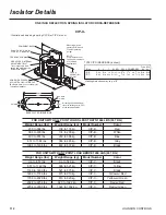
Page 112: ...Green Isolator Details CIP X ONE INCH DEFLECTION SPRING ISOLATOR CROSS REFERENCE Illustration shows single spring CIP B or CIP C mount HCL SBC Slot Width SW HCW MAX BOLT DIA MBD BASE PLATE DIMENSIONS...

Page 113: ...Steel Plate Top Bottom Neoprene covered to prevent corrosion L T H W D ENGLISH Size D H L T W BC CS MBD ND C 2 9 16 2 3 4 5 1 2 1 4 2 5 16 4 1 80 1 2 13 x 1 1 2 ND D 3 3 8 2 3 4 6 1 4 5 16 4 5 1 2 13...

Page 114: ...lbs 335 to 471 kg SLRS 2 C2 Green 1038 to 1497 lbs 471 to 679 kg SLRS 2 C2 Gray 1497 to 2058 lbs 679 to 933 kg SLRS 2 C2 Silver 2058 to 2619 lbs 933 to 1188 kg SLRS 2 C2 Gray w red 2619 to 3180 lbs 11...

Page 115: ...JOHNSON CONTROLS FORM 201 23 EG1 1007 115 INTENTIONALLY LEFT BLANK...

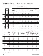
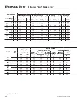
Page 116: ...3 0920 400 50 232 6 3 1 232 6 9 3 246 6 3 8 0267 460 60 191 6 2 8 380 60 242 6 3 5 242 6 9 3 1000 400 50 230 6 3 1 230 6 9 3 243 6 3 8 YCIV S P Control KVA 7 Unit Short Circuit Withstand KA Field Wir...

Page 117: ...3 206 5 3 8 160 5 2 8 203 5 3 5 203 5 9 3 192 5 3 1 192 5 9 3 204 5 3 8 191 6 2 8 242 6 3 5 242 6 9 3 230 6 3 1 230 6 9 3 243 6 3 8 High Head High Static Fans Two Speed Cond Fans Minimum Ckt Am pacit...

Page 118: ...80 6 9 3 189 6 3 8 0247 460 60 194 6 2 8 380 60 245 6 3 5 245 6 9 3 0930 400 50 233 6 3 1 233 6 9 3 246 6 3 8 YCIV E V Control KVA 7 Unit Short Circuit Withstand KA Field Wiring Protection Std Ultra Q...

Page 119: ...3 195 5 3 8 150 6 2 8 190 6 3 5 190 6 9 3 180 6 3 1 180 6 9 3 189 6 3 8 149 6 2 8 188 6 3 5 188 6 9 3 178 6 3 1 178 6 9 3 187 6 3 8 High Head High Static Fans Two Speed Cond Fans Minimum Ckt Am pacity...

Page 120: ...8 192 5 3 1 0397 460 60 191 6 2 8 191 6 2 8 380 60 241 6 3 5 241 6 9 3 241 6 3 5 1500 400 50 229 6 3 1 229 6 9 3 243 6 3 8 229 6 3 1 YCIV S P Control KVA 7 Unit Short Circuit Withstand KA Field Wirin...

Page 121: ...6 9 3 243 6 3 8 229 6 3 1 229 6 9 3 243 6 3 8 Field Wiring Protection Field Wiring Lugs High Head High Static Fans Two Speed Cond Fans STD Terminal Block OPT Circuit Breaker Max Inverse Time Ckt Brkr...

Page 122: ...5 3 8 183 5 3 1 0357 460 60 181 6 2 8 181 6 2 8 380 60 229 6 3 5 229 6 9 3 229 6 3 5 1380 400 50 218 6 3 1 218 6 9 3 229 6 3 8 218 6 3 1 YCIV S P Control KVA 7 Unit Short Circuit Withstand KA Field Wi...

Page 123: ...5 176 6 9 3 218 6 9 3 229 6 3 8 167 6 3 1 167 6 9 3 175 6 3 8 Field Wiring Protection Field Wiring Lugs High Head High Static Fans Two Speed Cond Fans STD Terminal Block OPT Circuit Breaker Max Inver...

Page 124: ...Circuit Breaker or Dual Element Fuse 225 of the largest compressor RLA plus the sum of all other loads per NEC 440 22 A 3 MCA Minimum Circuit Ampacity 125 of the largest compressor RLA plus 100 of the...

Page 125: ...NSON CONTROLS FORM 201 23 EG1 1007 125 FIG 1 two COMPressor WIRING DIAGRAM WITH CIRCUIT BREAKER 2 COMPRESSOR POWER WIRING CONNECTIONS FIG 2 two COMPressor WIRING DIAGRAM WITH TERMINAL BLOCK Power Wiri...

Page 126: ...gle Point FIG 4 Three COMPressor WIRING DIAGRAM WITH TERMINAL BLOCK Single Point 3 COMPRESSOR POWER WIRING CONNECTIONS VSD CONTROL PANEL VSD 2 VSD 3 STANDARD CONTROL TRANSFORMER UNIT CONTROLS EVAPORAT...

Page 127: ...JOHNSON CONTROLS FORM 201 23 EG1 1007 127 INTENTIONALLY LEFT BLANK...

Page 128: ...JOHNSON CONTROLS 128 Typical Control Wiring Two Compressor...

Page 129: ...JOHNSON CONTROLS FORM 201 23 EG1 1007 129 For informational purposes only Do not attempt to tie into wiring without a proper wiring diagram...

Page 130: ...JOHNSON CONTROLS 130 Typical Control Wiring Three Compressor...

Page 131: ...JOHNSON CONTROLS FORM 201 23 EG1 1007 131 For informational purposes only Do not attempt to tie into wiring without a proper wiring diagram...

Page 132: ...orporate the use of spring type isolators to minimize the transmission of vibration into building structure Additional support should be provided to the roof at the spring isolator locations Ground Lo...

Page 133: ...arrant all equipment and material of its manufacture against defects in workmanship and material for a period of eighteen 18 months from date of initial start up or date of availability 1 03 DELIVERY...

Page 134: ...her ent internal thermal overload protection and external current overload on all three phases C Lubrication External oil separators with no moving parts 450 PSIG design working pressure and UL listin...

Page 135: ...oss the line type starters will not be acceptable F Power Factor 1 Provide equipment with power factor correc tion capacitors as required to maintain a power factor of 95 at all load conditions 2 The...

Page 136: ...ct features Your Johnson Controls representative will be pleased to provide assistance A Sound Reduction 1 Provide the following options as required to meet scheduled sound performance data at all loa...

Page 137: ...tion Isolation Field Mounted 1 Neoprene Isolators 2 1 Inch Deflection Spring Isolators Level ad justable spring and cage type isolators for mounting under the unit base rails 3 2 Inch Deflection Seism...

Page 138: ...JOHNSON CONTROLS 138...

Page 139: ...JOHNSON CONTROLS FORM 201 23 EG1 1007 139...

Page 140: ...Form 201 23 EG1 1007 Supersedes 201 23 EG1 607 File in ET2...

Reviews: