Page 1 (of 7)
Installation and User Manual for Vice
HV 519 , 519S, 581
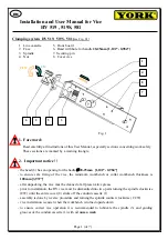
Clamping system HV 519, 519S, 581 (
see Fig. 1
) :
1. Line cassette
5. Front board
2. Face
6. Head with hole for handle
28-25mm [1,102“- 0,984“]
3. Spindle
7. Securing pin
4. Nut
8. Cover vice
1. Foreword:
Read carefully all instructions of this User Manual, especially sections concerning work safety.
These sections are marked by a warning triangle.
2. Important notice ! !
-
the head (6) has an opening for the hadle
∅
28-25mm [1,102“- 0,984“]
-
to ensure safe fixing of the vice, the minimum workbench or collar workbench thickness is
100mm [3,937“]
-
after unpacking, the vice must be cleaned of all preservative grease
-
prior to installation, the HV vice must be dismantled into two parts turning the spindle clockwise
(CW) until the entire cover (8) slides off the conduit cassette (1)
-
assembly is done by reverse procedure and turning the spindle counter clockwise (CCW)
-
vice installation is easier when the workbench is turned upside down
-
to ensure correct vice operation it is recommended to lubricate the spindle (3) and guiding
grooves of the conduit cassette (1) with oil
once a week
Fig. 1
2
4
5
3
1
6
7
CCW
CW
EN
8


