


FORM 160.49-M1
35
YORK INTERNATIONAL
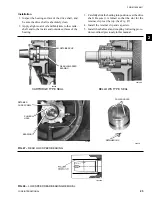
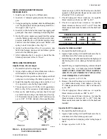
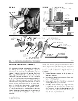
4. Apply a light coating of oil and Molykote onto the
eye of the impeller where it enters the eye seal ring.
5. Using proper rigging methods, raise the rotor sup-
port with motor adapter into proper position, and
slide it into place over the guide pins.
6. Carefully slide the rotor support into place against
the scroll housing. Use care that the impeller is not
damaged as it enters the eye seal ring.
7. Insert the cap screws and tighten to the proper
torque. (See Table 4)
8. Re-install the compressor coupling.
9. Bolt the motor to the motor adaptor.
10. Re-connect all external piping.
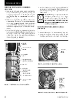
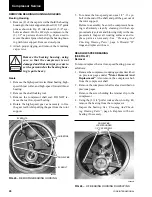
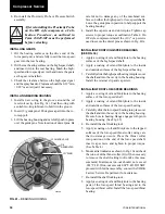
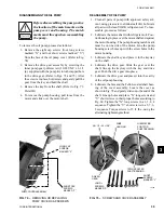
REMOVING THE PRE-ROTATION VANE HOUSING
The Pre-Rotation Vane Assembly cannot be removed
from the suction connection side of the compressor on
the HA, HB and HD style compressors. The rotor sup-
port must first be removed from the rotor scroll and the
rotor scroll dissembled as described previously.
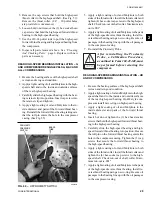
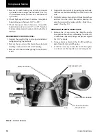
On the HF style compressor, access to the PRV assem-
bly can be made by removing the suction piping and re-
moving the cap screws that secure the PRV plate sup-
port to the rotor scroll. Insert proper guide pins and using
proper rigging methods, remove PRV support plate from
compressor scroll to gain access to the PRV assembly.
(See Fig. 69)
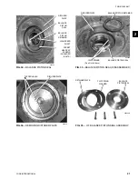
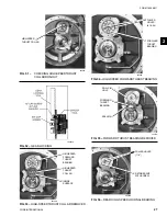
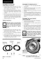
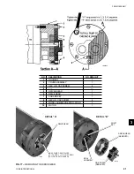
FIG. 71 –
PRE-ROTATION VANE
HOUSING ASSEMBLY
26667A
LD05191
ITEM
DESCRIPTION
QTY.
ITEM
DESCRIPTION
QTY.
NO.
NO.
1
Ring, Driving
1
7
Washer
10
2
Vane
9
8
Stud, Ball
9
3
Retainer
9
9
Screw – 12 pt.
9
4
Arm, Vane
9
10
Screw – Hex HD
18
5
Spacer, Arm
9
11
Nut, Self-Locking
9
6
Washer
9
12
Housing
1
2
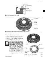
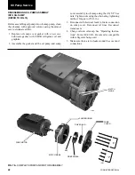
FIG. 70 –
INTERNAL PARTS - PRE-ROTATION
VANE ASSEMBLY
26666A
PRE-ROTATION
VANE DRIVING RING
INTERNAL LEVER
FIG. 69 –
REMOVING HF PRV SUPPORT PLATE
00593VIP
GUIDE PIN
PRV SUPPORT
PLATE


