


YORK INTERNATIONAL
24
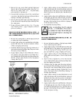
REMOVING BEARING HOUSING AND GEARS
Bearing Housing
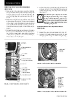
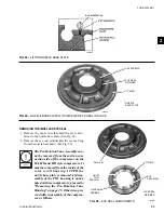
1. Remove (2) of the cap screws that hold the bearing
housing to the rotor support and insert (2) 3/8" guide
pins as shown in Fig. 45. Also insert (3) 3/8" eye-
bolts as shown. On the HF style compressors, the
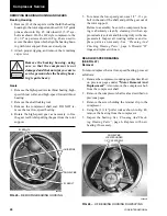
(2) 1/2" cap screws shown in Fig. 46 are used to
secure the dowel pins which align the bearing hous-
ing with rotor support. Remove dowel pins.
2. Attach proper rigging, and remove the remaining
cap screws.
Remove the bearing housing, using
care so that the compressor is not
damaged and that no injury occurs to
service personnel as the bearing hous-
ing is quite heavy.
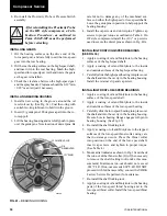
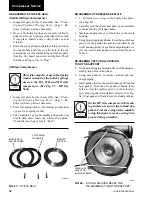
Gears
1. Remove the high-speed reverse thrust bearing, high-
speed thrust collar, and high-speed forward thrust
bearing.
2. Remove the shaft locking tool.
3. Remove the compressor shaft seal. DO NOT re-
move the rear low-speed bearing.
4. Rotate the high-speed gear as necessary to free
the gear teeth while pulling the gear from the rotor
support.
5. To remove the low-speed gear, use a 1/2" - 13 eye-
bolt in the end of the shaft and pull the gear out of
the rotor support.
Before re-assembly, be sure the compressor hous-
ing is absolutely clean by cleaning it with an ap-
proved safety solvent and blowing it dry with com-
pressed air. Inspect all wearing surfaces and re-
place parts as necessary. See
“Cleaning And
Checking Wearing Parts”
, page 6. Discard “O”
rings and replace with new.
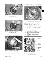
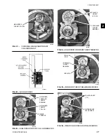
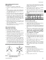
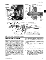
REAR LOW-SPEED BEARING
(SEE FIG. 47)
Removal
To remove/replace the rear low-speed bearing, proceed
as follows:
1. Remove the compressor coupling spool as described
on previous pages under
“Motor Removal And
Replacement”
. Also remove the compressor hub
from the compressor shaft.
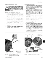
2. Remove the compressor shaft seal as described on
previous pages.
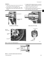
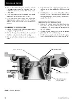
3. Remove the screw holding the retainer clip to the
compressor.
4. Using the (2) 1/4" puller rods as shown in Fig. 48,
remove the bearing from the compressor.
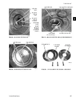
5. Inspect the bearing. See
“Cleaning And Check-
ing Wearing Parts”
, page 6. Replace with new
bearing if necessary.
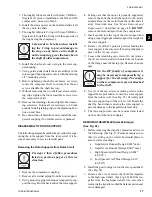
EYEBOLTS
GUIDE PINS
DOWEL PINS
EYEBOLT
26329A
FIG. 45 –
REMOVING BEARING HOUSING
Compressor Service
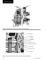
FIG. 46 –
HF BEARING HOUSING DOWEL PINS
00590VIP
DOWEL PINS
LOCATED UNDER
1/2" CAP SCREWS


