


YORK INTERNATIONAL
32
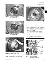
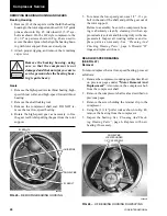
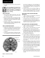
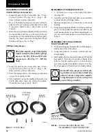
5. Remove the shaft locking tool and check rim and
eye radial runout using a dial indicator. (See Fig.
27). Maximum runout on rim is .003" and runout on
eye is .002".
6. Check high-speed thrust clearance. Acceptable
thrust tolerance is between .009" to .020".
7. Check low-speed thrust clearance. Acceptable
thrust tolerance is between .011" to .019". Note that
this measurement must be taken with the shaft seal
installed.
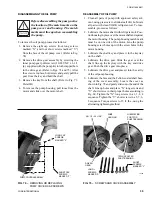
DISASSEMBLY OF ROTOR SCROLL
1. Support the weight of the rotor support and motor
using proper rigging methods.
2. Remove the cap screws that fasten the suction and
discharge connections to the scroll housing.
3. Remove all other external piping from the rotor
scroll.
4. Support the rotor scroll by proper rigging methods;
then remove the bolts holding the rotor scroll to the
unit.
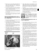
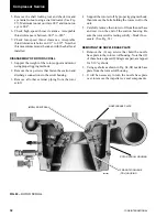
5. Carefully remove the rotor scroll from the unit base
and rest it on the end of the suction housing. Be
sure the rotor scroll is resting solidly – block if nec-
essary. (See Fig. 63)
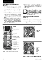
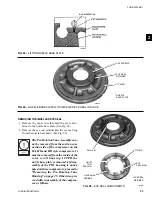
REMOVING THE NOZZLE BASE PLATE
1. Remove the (6) cap screws that hold the nozzle
base plate to the rotor scroll housing. Note that (2)
of these holes, spaced 180 degrees apart, are tapped
for 5/16" eyebolts.
2. Using eyebolts as shown in Fig. 64, lift nozzle base
plate from the rotor scroll housing.
3. It will be necessary to turn the nozzle base plate
over to remove the impeller eye seal components.
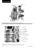
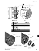
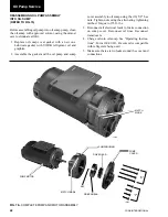
FIG. 63 –
ROTOR SCROLL
26439A3
PRE-ROTATION VANE
(PRV) HOUSING
ROTOR SCROLL HOUSING
NOZZLE BASE PLATE
IMPELLER EYE SEAL
Compressor Service


