

279747-YTG-A-0407
Unitary Products Group
5
HORIZONTAL SIDEWALL VENTING
For applications where vertical venting is not possible, the
only approved method of horizontal venting is the use of an
auxiliary power vent. Approved power venters are Fields
Controls Model SWG-4Y or the appropriate Tjernlund GPAK
model. Follow all application and installation details provided
by the manufacturer of the power vent. This unit may be hori-
zontally vented using 4” (10.2 cm) diameter pipe with a mini-
mum length of 4.5 feet (1.37 m) and a maximum length of
34.5 feet (10.82 m) with up to 4 elbows.
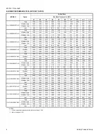
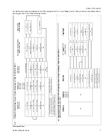
FILTER PERFORMANCE
The airflow capacity data published in Blower Performance
Tables above, represents blower performance WITHOUT fil-
ters. To determine the approximate blower performance of
the system, apply the filter drop value for the filter being used
or select an appropriate value from the Table below.
NOTE:
The filter pressure drop values in Blower Perfor-
mance Tables are typical values for the type of filter listed and
should only be used as a guideline. Actual pressure drop rat-
ings for each filter type vary between filter manufacturer.
NOTES:
1. Air velocity through throwaway type filters may not exceed 300
feet per minute. All velocities over this require the use of high
velocity filters.
APPLYING FILTER PRESSURE DROP TO
DETERMINE SYSTEM AIRFLOW
To determine the approximate airflow of the unit with a filter in
place, follow the steps below:
1.
Select the filter type.
2.
Select the number of return air openings or calculate the
return opening size in square inches to determine the
proper filter pressure drop.
3.
Determine the External System Static Pressure (ESP)
without the filter.
4.
Select a filter pressure drop from the table based upon
the number of return air openings or return air opening
size and add to the ESP from Step 3 to determine the
total system static.
5.
If total system static matches an ESP value in the airflow
table (i.e. 0.20, 0.60, etc,) the system airflow corre-
sponds to the intersection of the ESP column and Model/
Blower Speed row.
6.
If the total system static falls between ESP values in the
table (i.e. 0.58, 0.75, etc.), the static pressure may be
rounded to the nearest value in the table determining the
airflow using Step 5 or calculate the airflow by using the
following example.
Example:
For a 60,000 Btuh furnace operating on high
speed blower, it is found that total system static is 0.58" w.c.
To determine the system airflow, complete the following
steps:
1.
Obtain the airflow values at 0.50" & 0.60" ESP.
Airflow @ 0.50": 1240 CFM
Airflow @ 0.60": 1170 CFM
2.
Subtract the airflow @ 0.50" from the airflow @ 0.60" to
obtain airflow difference.
1170 - 1240 = -70 CFM
3.
Subtract the total system static from 0.50" and divide this
difference by the difference in ESP values in the table,
0.60" - 0.50", to obtain a percentage.
(0.58 - 0.50) / (0.60 - 0.50) = 0.8
4.
Multiply percentage by airflow difference to obtain airflow
reduction.
(0.8)x(-70) = -56
5.
Subtract airflow reduction value to airflow @ 0.50" to
obtain actual airflow @ 0.58" ESP.
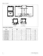
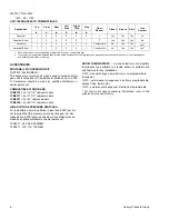
RECOMMENDED FILTER SIZES
Cabinet Size
Top Return (in)
A
(2) 14 x 20
B
(2) 14 x 20
C
(2) 14 x 20
D
(2) 14 x 20
FILTER PERFORMANCE - PRESSURE DROP INCHES W.C. AND (KPA)
Airflow Range
Minimum
Opening Size
Filter Type
Disposable
Washable Fiber
Pleated
CFM
in
2
In W.C.
In W.C.
In W.C.
0 - 750
230
0.01
0.01
0.15
751 - 1000
330
0.05
0.05
0.20
1001 - 1250
330
0.10
0.10
0.20
1251 - 1500
330
0.10
0.10
0.25
1501 - 1750
380
0.15
0.14
0.30
1751 - 2000
380
0.19
0.18
0.30
2001 & Above
463
0.19
0.18
0.30


