


035-15241-003 Rev. A (201)
16
Unitary Products Group
ACCESSORIES
A humidifier or electronic air cleaner may be used with this
furnace. All accessories should be wired according to the
manufacturer's instructions.
The furnace control board has a terminal marked EAC, which
may be used to power an electronic air cleaner accessory.
This terminal is energized with 115 volts whenever the fur-
nace circulating air blower is operating in either heating or
cooling speed.
The furnace control board has a terminal marked HUM, which
may be used to power an humidifier accessory. This terminal
is energized with 115 volts whenever the wall thermostat calls
for heat.
Make sure that the total load on the furnace transformer does
not exceed 40 VA, including gas valve, furnace relays, acces-
sories, and air conditioner loads.
Do not attempt to wire an electronic air cleaner into the fur-
nace blower relay. Damage to the furnace blower motor may
result.
TWINNING
When two furnaces are installed using the same duct system,
it is very important that the two furnace circulating air blowers
operate simultaneously. If one blower starts before the sec-
ond blower, the duct system will become pressurized with air
and the second blower will be made to turn backwards. Dur-
ing heating operation, this will cause overheating of the sec-
ond furnace, possibly causing an unsafe condition and
damage to the furnace. The furnace control board has a ter-
minal marked TWIN which can be used to cause two furnace
blowers to operate together.
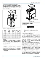
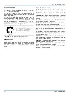
If two furnaces are to be twinned using a single wall thermo-
stat, connect an isolation relay as shown in Figure 12 below.
BLOWER MOTOR SPEED SELECTION
These furnaces are equipped with blowers, which have multi-
speed direct drive motors.
The blower speed selected is dependent upon the design
and static pressure loss of the duct system. The duct system
external static pressure includes the combined total of the
supply and return ducts and any plenum type air conditioning
coil if used.
The furnace must be adjusted to operate at or below the
maximum external static (in. W.C.), and within the air temper-
ature rise range as shown on the unit rating plate and in the
specification table.
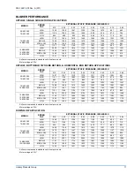
Dependent upon the conditions in a particular installation, the
blower speeds may need to be changed to give the proper
operation on cooling or heating. The table above shows the
proper blower speed to use for cooling operation.
These leads should be connected in the control box to either
the heating terminal or the cooling terminal, depending on the
airflow desired. The unused motor speed lead(s) should be
connected to the terminals marked PARK on the blower con-
trol board in the furnace control box.
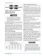
FIGURE 12: TWIN CONNECTION DIAGRAM
W
G
C
R
Y
TWIN
TO A/C
WALL THERMOSTAT
W
G
R
Y
ISOLATION
RELAY
FURNACE 2 CONTROL BOARD
W
G
C
R
Y
TWIN
FURNACE 1 CONTROL BOARD
SHOCK HAZARD -
Be sure electrical power to
furnace is turned off before changing motor
speeds.