


035-15241-003 Rev. A (201)
12
Unitary Products Group
Unless prohibited by local codes, it is permissible to use a
flexible corrugated metal gas connector for the last section of
gas piping connected to the furnace gas valve. If a flexible
connector is used, it must be certified to be in compliance
with ANSI Standard Z21.24 or, in Canada, with Standard
CAN1-6.10.
Following installation of the piping, first ensure that the gas
control lever or switch on the gas valve is in the off position
and then pressurize the system with gas. Thoroughly check
the piping system for leaks.
The maximum and minimum gas supply pressure required at
the inlet of the gas control valve is shown on the unit rating
plate. When the furnace is in operation, the inlet pressure
must be within the limits shown.
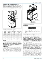
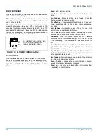
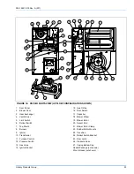
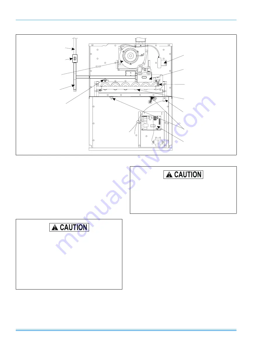
FIGURE 11: UPFLOW/HORIZONTAL (150 MBH MODEL ONLY)
BLOWER
DOOR
SWITCH
ROLL-OUT
SWITCHES
BURNERS
HOT
SURFACE
IGNITOR
GAS
VALVE
PRESSURE
SWITCH
GAS
PIPE
GAS
SHUT-OFF
VALVE
ROLL-OUT
SWITCH
DIRT
LEG
VENT
BLOWER
FURNACE
CONTROL
During pressure testing of the gas supply piping
system, observe the following to avoid fire, explo-
sion, asphyxiation, or damage to the appliance.
a.
If test pressure is less than or equal to 1/2 psig
(3.48 kPa)(14" W.C.), isolate the furnace by clos-
ing its individual manual shutoff valve.
b.
If test pressure is greater than 1/2 psig (3.48
kPa)(14" W.C.), the furnace and its individual
shutoff valve must be disconnected from the gas
supply system.
Never use an open flame to check for leaks. Fire
or explosion could occur. Since some leak solu-
tions, including soap and water, may cause corro-
sion or stress cracking, the piping must be rinsed
with water after testing unless it has been deter-
mined that the leak solution is non-corrosive.