4
controlled by microswitches (0, 60, 90 minutes). Factory-set
to 0 minutes.
Defrost can be carried out only when the unit is in heat pump
operation.
Start:
The following conditions should exist:
- The compressor is in operation.
- The liquid probe temperature is below -° C for minutes,
or for 5 minutes if the outdoor temperature is below -5° C.
- That the time period from the last defrost, 0 minutes, has
expired.
Operating procedure:
When starting defrost, the following operations are carried
out:
- The 4-way valve is set to cool mode.
- The outdoor fan is turned off.
- The YKlon board call manager will decide whether another
heat stage can be started.
- During defrost, do not turn off the compressor that is de-
frosting, even if called for by the thermostat.
- The indoor fan will turn off if there is no stage that can pro-
duce heat, and microswitch No. 8 is set to OFF. If set to ON,
the indoor fan does not turn off. (Set to ON by default.)
End:
The operating procedure will last until one of the following
conditions is present:
- Liquid temperature above 1° C for 2 seconds.
- Liquid temperature above 5° C for 0 seconds.
- Liquid temperature above 2° C for 2 minutes.
- Time expired since the start of the defrost over 10
minutes.
- A high pressure switch failure signal is generated.
- If liquid temperature drops below -25° C.
Operating procedure:
When the defrost is finished:
- The outdoor fan turns on and remains in standby for 10
seconds.
- The four-way valve is set to heat.
- The call manager will decide whether or not the compressor
is to remain in operation.
To eliminate the drops of water from the coil, the outdoor
fan will remain in operation for one minute, even if there is
no call.
Simultaneous defrost of two stages is not allowed, and one
of these remains in standby until the operating procedure of
the other is over.
17 - Safety features and controls
17.1.- Cooling lock-out
The cooling circuit is protected against high pressure (HP),
low pressure (LP), discharge temperature and repeated starts
in cool by means of a suction probe in the summer cycle.
If a failure is detected, thermostat DPC-1 indicates the
cooling circuit affected (two numbers) and type of failure.
Furthermore, the YKlon board alarm relay is activated, with
24 VAC phase R at terminal AL.
If the cause of the failure has disappeared, the failure can be
reset from the thermostat by setting the thermostat to OFF
and then back to ON. Only three resets can be carried out
in 24 hours.
17.2.- Gas heating lock-out (models D4IG)
In the case of IC1, IC2 control lock-out due to the activation
of any of the LS11, LS21 (automatic reset thermal switch),
RS11, RS12, RS21, RS22 (burner manual reset thermal
switch) or AS1, AS2 (air pressure switch) devices, the control
will remain in lock-out until the activated device is re-estab-
lished and a reset is carried out. In the case of a lock-out due
to non-detection of a flame, control IC1 generates an alarm
and the gas board can carry out a maximum of 5 resets. Then
the gas control will be locked out and thermostat DPC-1 will
display the failure.
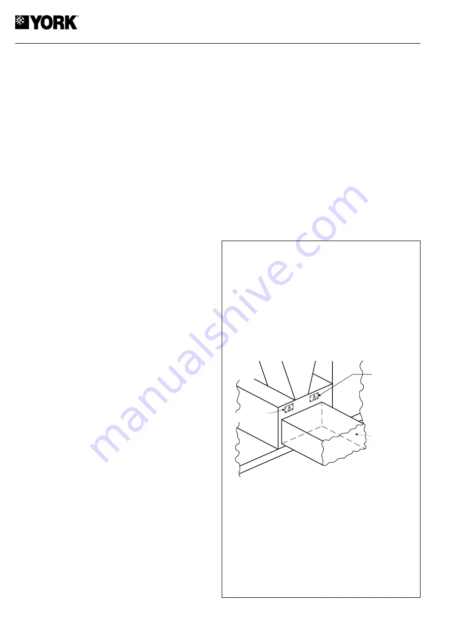
If the manual reset thermal switch LS1 opens, the start-up
control will not be operative until it is reset manually.
Thermal switch LS1 can be accessed through the cover on
the side panel of the unit, on the side opposite to the burner
assembly access doors, right over the opening for the con-
nection of the side impulse duct (see Fig. 17).
- Fig. 17 -
ACCESS COVER
LS1, LS11
AND IMPULSE
PROBE, B8
SIDE
IMPULSE
DUCT
ACCESS COVER
LS21
Summary of Contents for D4IC-360
Page 2: ......
Page 43: ...43 20 Wiring diagrams 20 1 Cool only models D4IC 360 D4IC 360G50 400 3 50 1 of 3 ...
Page 44: ...44 D4IC 360G50 400 3 50 2 of 3 ...
Page 45: ...45 D4IC 360G50 400 3 50 3 of 3 ...
Page 46: ...46 20 2 Cool only models D4IC 480 D4IC 480G50 400 3 50 1 of 3 ...
Page 47: ...47 D4IC 480G50 400 3 50 2 of 3 ...
Page 48: ...48 D4IC 480G50 400 3 50 3 of 3 ...
Page 49: ...49 20 3 Heat pump models B4IH 360 400 3 50 1 of 3 ...
Page 50: ...50 B4IH 360 400 3 50 2 of 3 ...
Page 51: ...51 B4IH 360 400 3 50 3 of 3 ...
Page 52: ...52 20 4 Heat pump models B4IH 480 400 3 50 1 of 3 ...
Page 53: ...53 B4IH 480 400 3 50 2 of 3 ...
Page 54: ...54 B4IH 480 400 3 50 3 of 3 ...
Page 55: ...55 20 5 Cool only gas heating models D4IG 360 400 3 50 1 of 4 ...
Page 56: ...56 D4IG 360 400 3 50 2 of 4 ...
Page 57: ...57 D4IG 360 400 3 50 3 of 4 ...
Page 58: ...58 D4IG 360 400 3 50 4 of 4 ...
Page 59: ...59 20 5 Cool only gas heating models D4IG 480 400 3 50 1 of 4 ...
Page 60: ...60 D4IG 480 400 3 50 2 of 4 ...
Page 61: ...61 D4IG 480 400 3 50 3 of 4 ...
Page 62: ...62 D4IG 480 400 3 50 4 of 4 ...
Page 63: ...63 Configuration of switches Data and dimensions are subject to change without prior notice ...
Page 64: ...www johnsoncontrols com ...


