


YORK INTERNATIONAL
9
FORM 160.49-O1
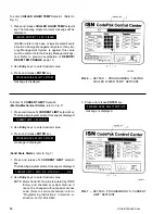
Continuously pressing this key will display the mo-
tor current and line voltage alternately. When used
with the DISPLAY HOLD key, motor current and
line voltage will alternately be displayed each time
this key is pressed. The messages are as follows:
A AMPS = XXXX; B AMPS = XXXX; C AMPS = XXXX
V A-B = XXXX; V B-C = XXXX; V C-A = XXXX
If chiller is not equipped with a Solid State Starter,
this key produces the following message:
SOLID STATE STARTER NOT INSTALLED
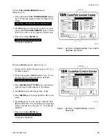
In PROGRAM mode, this key is used to display
the applicable line voltage range (200-208VAC, 220-
240VAC, 380VAC, 400VAC, 415VAC, 440-480VAC,
500-600VAC, Supply Voltage Range Disabled). The
correct line voltage range is programmed at the
YORK factory and is checked by the service tech-
nician at start-up. For security reasons, a special
access code is required to program the line volt-
age range. The line voltage range is used to deter-
mine a low line voltage threshold for cycling shut-
down. Refer to “System Setpoints” for Trip/Reset
values.
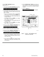
To Display CONDENSER LIQUID TEMPERATURES
(Field Installed Option Package):
Use CONDENSER LIQUID TEMPS display key as
described above to produce the following alphanu-
meric display message:
COND LEAVING = XXX.X°F; RETURN = XXX.X°F
– or –
COND LEAVING = XXX.X°C; RETURN = XXX.X°C
NOTE: If the condenser liquid thermistors are not con-
nected, or both thermistors are “out of range”,
the display will blank when this key is pressed.
To Initiate a PRINT to Printer:
Press the PRINT key to initiate a printout to an
optional printer. When the key is pressed,
PRINT ENABLE
is displayed.
Refer to “MicroComputer Control Center – System
Status Printers” instruction, Form 160.49-N2 for de-
tails of the optional printers.
To Display MOTOR CURRENT:
Press the % MOTOR CURRENT display key as
described above to display motor current as a per-
cent of Full Load Amps (FLA). The message is as
follows:
MOTOR CURRENT = XXX% FLA
NOTE: • Liquid-Cooled Solid State Starter Applica-
tions – the % Motor Current displayed is the
highest of three line currents divided by the
programmed chiller FLA value x 100%.
• Electro-Mechanical Starter Applications –
the % Motor Current displayed is the highest
of the three line currents.
To Display OPERATING HOURS and STARTS
COUNTER:
Use the OPERATING HOURS key as described
on page 7, to produce the following message:
OPER. HOURS = XXXXX; START COUNTER = XXXXX
NOTE: The operating hours and starts counter can be
reset to zero. Refer to “Programming the Mi-
croComputer Control Center”, page 13. How-
ever, the purpose of the OPERATING HOURS
key is to display the total accumulated chiller
run time. Therefore, the operating hours should
not be arbitrarily reset.
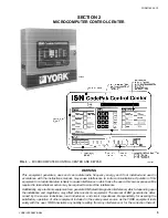
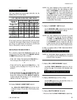
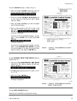
SYSTEM SETPOINTS
The system setpoints may be programmed by the sys-
tem operator. The Setpoint keys are located on the
Control Center keypad (see Fig. 3). To program, see
“Programming System Setpoints”, page 13. The fol-
lowing is a description of these setpoints (with the En-
glish/Metric jumper installed on the Micro Board):
CHILLED LIQUID TEMP – This key displays the leav-
ing chilled water temperature (LCWT) setpoint in de-
grees Fahrenheit. If not programmed, the default value
is 45°F (17.2°C). See “Programming System Setpoints”,
page 14).
NOTE: If an Energy Management System is interfaced
to the Control Center for the purpose of re-
mote LCWT setpoint reset, then the operator-
programmed chilled liquid temperature will be
the base or lowest setpoint available to the
Energy Management System (EMS). This
chilled liquid temperature value must also be
entered into the EMS. Further, any subsequent
change to this value must also be entered into
the EMS.


