


YORK INTERNATIONAL
25
FORM 160.49-O1
VANE MOTOR SWITCH OPEN
The chiller is shut down because a system-start se-
quence has been initiated, but the pre-rotation vanes
are not fully closed.
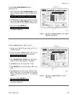
MON XX:XX AM – STARTER MALFUNCTION DETECTED
The chiller is shut down because the Control Center
has detected a motor-current value greater than 15%
FLA for 10 seconds minimum anytime when the com-
pressor-start signal is not energized. To restart the
chiller, press COMPRESSOR switch to STOP/RESET
position and then to the START position.
MON XX:XX AM – PROGRAM INITIATED RESET
The chiller is shut down because Micro Board did not
receive a hardware-generated interrupt on schedule.
Typical is an Analog/Digital Converter interrupt. This
message is indicative of a Micro Board hardware fail-
ure or electrical noise on Micro Board. The chiller will
automatically restart. This message indicates that the
watchdog timer-circuit has reset the microprocessor.
This occurs when the time needed to step through pro-
gram is longer than allowable, thus the software pro-
gram is initialized at its beginning.
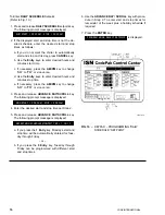
SYSTEM READY TO START – PRESS STATUS
The chiller was shut down on a safety shutdown and
will start upon application of a local or remote start
signal. Since the message states that the chiller is
“Ready to Start”, it means that the shutdown no longer
exists and the Control Center has been manually re-
set. When the STATUS key is pressed, a message is
displayed that describes the reason for shutdown. The
message will be displayed for 2 seconds and then re-
turn to
SYSTEM READY TO START – PRESS STATUS
.
Those messages that could be displayed are any of
the previously described safety-shutdown messages
or warning messages. They can be cleared from the
display by entering Service mode and pressing WARN-
ING RESET key. Or, the message will be cleared by
initiating a compressor start.
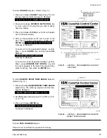
START SEQUENCE INITIATED
Indicates that the Micro Board has received a local or
remote start signal and has initiated the chiller start-
up routine.
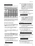
This is the compressor pre-lube period. The duration
of this period is controlled by the “Prerun” (JP6) wire
jumper on the Micro Board as follows:
FUNCTION
JUMPER POSITION
50 Sec. Oil Pump Prerun
Installed
180 Sec. Oil Pump Prerun
Cut
SYSTEM COASTDOWN
Displayed while motor is decelerating after a chiller
shutdown. The oil pump is running during this period.
The duration of this period is 150 seconds.
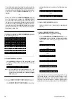
MON XX:XX AM – MTR PHASE CURRENT UNBALANCE
(Solid State Starter applications only)
The chiller is shut down because the compressor-motor
current was unbalanced while the chiller was running.
The current balance is only checked after the motor
has been running for a minimum of 45 seconds and the
motor current is 80% FLA or greater. If the current in
any phase deviates from the average (
a + b
3
+ c
) current
by greater than 30% for a minimum of 45 consecutive
seconds, a shutdown is initiated. To restart the sys-
tem, press the COMPRESSOR switch to STOP/RE-
SET position and then to the START position. An ex-
ample of the conditions for shutdown is as follows:
IF:
I
∅
A
= 200A
I
∅
B
= 200A
I
∅
C
= 118A
THEN:
I
AV
=
200 + 200 + 118
3
I
AV
= 173A
I
ACCEPTABLE
= 173
±
30% = 121A or 225A
THEREFORE:
Since I
∅
C
= 118A which is less than the accept-
able 121A, the chiller would shut down if this
unbalance exists for 45 consecutive seconds.
MON XX:XX AM – LOW LINE VOLTAGE
(Solid State Starter applications only)
Chiller is shut down because the voltage in any phase
of line voltage has decreased below the under-volt-
age-shutdown threshold for 20 consecutive seconds,
or failed to achieve the minimum required starting line-
voltage. Refer to explanation under “System Setpoints
– SSS Motor Current/Volts”, page 10. The system will
automatically restart when all phases of line voltage
increase to the minimum required starting voltage.


