background image

5292154-UIM-A-0317

Johnson Controls Unitary Products

5

Upflow or downflow applications (CF/CM Models):

These coils are factory shipped for installation in either upflow or down-
flow applications with a minor conversion.

1.

Position the coil cabinet on the furnace or modular air handler
opening (or the coil cabinet under the furnace or modular air han-
dler opening for appropriate air flow) as shown in Figure 5 or 6.

2.

Use the three tie plates and screws (included in bag with coil) to
secure the coil cabinet to the furnace or modular air handler.

3.

Seal mating surfaces to prevent air leakage between the coil cabi-
net and the furnace or modular air handler.

4.

Place the three duct flanges (from bag with coil) in mounting posi-
tions of the upper air flow opening on the coil, and secure with
screws from the bag as shown in Figure 4. 

5.

See sections on “Refrigerant Line Connections” and “Condensate
Drain Connections” for further installation instruction.

Horizontal applications (CM Models only):

CM model coils are supplied ready to be installed in a horizontal left
position. A horizontal drain pan is factory installed. If horizontal right
application, refer to the horizontal right conversion before proceeding.

1.

Position the coil cabinet against the furnace or modular air handler
opening as shown in Figure 8, 9, 11, or 12.

2.

Use the three tie plates and screws (included in bag with coil) to
secure the coil cabinet to the furnace or modular air handler.

3.

Seal mating surfaces to prevent air leakage between the coil cabi-
net and the furnace or modular air handler.

4.

Install the three duct flanges with screws (from bag with coil) in
positions shown in Figure 4.

5.

See sections on “Refrigerant Line Connections” and “Condensate
Drain Connections” for further installation instruction.

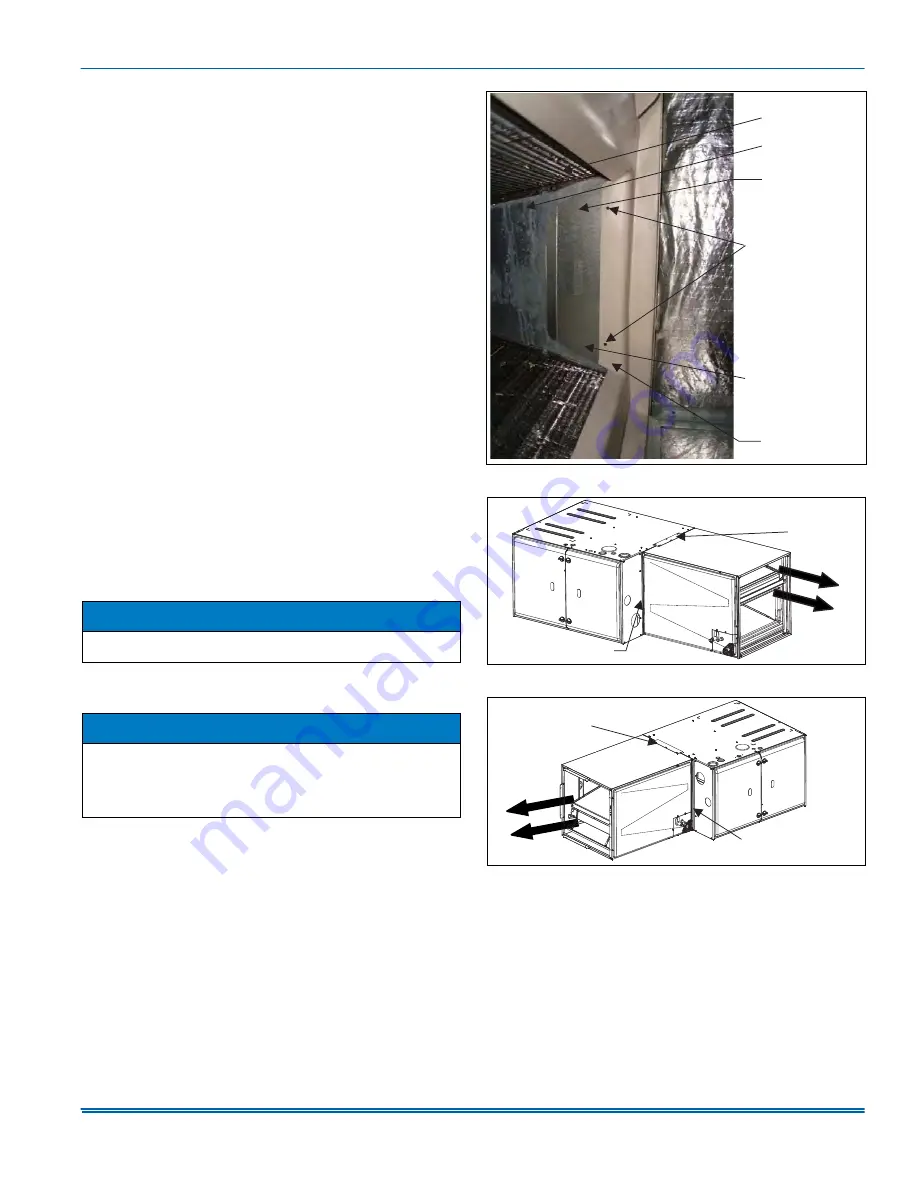
Horizontal right conversion (CM Models only):

1.

Remove coil access panel.

2.

Slide coil/drain pan assembly out of coil cabinet.

3.

Install the front and the back coil blow off wings (apply only to “N”
coils) in accordance with the following: 

a.

Locate 4 screws (2 front side and 2 back side) securing the
coil delta plates to the coil drain pan.

b.

Loosen each screw.

c.

Slide each coil blow off wing between the drain pan and the
coil delta plate.

d.

Tighten screw to secure coil blow off wings. See Figure 7.

4.

Slide the coil back into the cabinet. Be sure to engage the side coil
slide into the slide rail on the coil cabinet.

5.

Install coil access panel. The horizontal right conversion is now
complete. Return to and accomplish the horizontal application
installation.

SECTION IV: DIRECT DUCT 

INSTALLATION (CF MODELS)

In cases where the coil is being removed from the provided casing and
installed directly into the ductwork, the shroud (a Source 1 part), must
be installed. The top right blow off shield is removed, and the shroud is
installed by attaching it to the top of the coil and to the front and aft seal
plates. See Figure 10 for details.

NOTICE

Convert coil to correct orientation prior to installation. Conversion
must be made before brazing the refrigerant connections to the coil.

NOTICE

When installing a coil blow off wing, make sure that each notch in the
coil blow off wing slides around the anchor screw with the bottom of
the notch fully set against the screw. 
Ensure that coil blow off wing is installed with the flange bending
away from the coil delta plate. blow off wings only apply to “N” coils.

 FIGURE 7:  

Coil Blow Off Wing Installation

 FIGURE 8:  

CM Horizontal Right Application with Furnace

 FIGURE 9:  

CM Horizontal Left Application with Furnace

,167$//&2,/%/2:
2)):,1*21)5217
$1'%$&.2)&2,/

&2,/

'(/7$3/$7(

'5$,13$1

6&5(:6
SHUEORZRIIZLQJ

%/2:2)):,1*

$

)851$&(

&2,/

$

7,(3/$7(

75$16,7,21$1*/(

)851$&(

&2,/

$

7,(3/$7(

75$16,7,21$1*/(

Summary of Contents for CF18A

Page 1: ...ure Drop for CF Models 12 SECTION I GENERAL This instruction covers the installation of the following coils with fur naces or MP ME MVC modular air handlers The coils have sweat connect fittings All coils are shipped with a low psi nitrogen holding charge See Figures 1 SECTION II SAFETY This is a safety alert symbol When you see this symbol on labels or in manuals be alert to the potential for per...

Page 2: ...HQ UHFHLYHG A0267 001 COIL ACCESS PANEL VERTICAL POSITION SECONDARY DRAIN VERTICAL OR HORIZONTAL POSITION PRIMARY DRAIN HORIZONTAL POSITION SECONDARY DRAIN VAPOR LINE LIQUID LINE LOCATION TABLE 1 Dimensions CF Upflow Downflow Full Cased Coils Models1 1 Asterisk denotes coil model is available as a flex coil or with factory installed TXV Dimensions 2 2 All dimensions are in inches Refrigerant Conne...

Page 3: ... CM18A 19 1 2 14 1 2 13 1 2 13 1 2 3 8 3 4 CM18B 19 17 1 2 16 1 2 16 1 2 CM24A 19 1 2 14 1 2 13 1 2 13 1 2 CM24B 19 17 1 2 16 1 2 16 1 2 CM24C 21 21 20 20 CM25B 25 5 8 17 1 2 16 1 2 16 1 2 CM30A 25 1 2 14 1 2 13 1 2 13 1 2 CM30B 23 17 1 2 16 1 2 16 1 2 CM30C 23 21 20 20 CM30D 25 24 1 2 23 1 2 23 1 2 CM36A 25 1 2 14 1 2 13 1 2 13 1 2 CM36B 25 5 8 17 1 2 16 1 2 16 1 2 CM36C 25 21 20 20 CM36D 25 24 1...

Page 4: ...ront of cabinet 2 Remove two screws from top front side of cabinet 3 Remove transition angle rotate angle 180 end for end and secure to top front side of cabinet 4 For installation with modular air handling unit remove the transition angle and discard it FIGURE 3 Component Location Cased Coil CM Model TABLE 3 Coil Air Flow Limits Coil 1 Size 1 Asterisk denotes coils only available with Factory Mou...

Page 5: ...Drain Connections for further installation instruction Horizontal right conversion CM Models only 1 Remove coil access panel 2 Slide coil drain pan assembly out of coil cabinet 3 Install the front and the back coil blow off wings apply only to N coils in accordance with the following a Locate 4 screws 2 front side and 2 back side securing the coil delta plates to the coil drain pan b Loosen each s...

Page 6: ... system or filter and will not be exposed to freezing temperatures Instruct the owner that the indoor coil drain pan should be inspected and cleaned regularly to prevent odors and assure proper drainage Coils should be installed level or pitched slightly toward the drain end Suggested pitch should not exceed 1 4 inch per foot of coil Drain plugs can be removed using a standard 3 8 drive socket rat...

Page 7: ...nd isolated by using appropriate hangers or strapping SECTION VIII COIL METERING DEVICES A piston or a TXV flex coil models is to be installed in the field There is an installation manual that comes with the TXV kit It is recommended to install the piston or TXV kit prior to installation of coil and brazing of line set Until brazing is completed and cooled the TXV sensing bulb must not be installe...

Page 8: ...the distributor assembly with supplied fittings Ensure Teflon washer is seated in distributor Hand tighten and turn an additional 1 4 turn to seal Do not over tighten fittings See Figure 16 5 Slide the nut removed in step 3 over the supplied liquid line Place supplied Teflon washer from TXV kit in place on TXV and install liq uid line to the top of the thermal expansion valve Adjust assembly so li...

Page 9: ...ILS Coils equipped with an EEV are available for use with a fully modulating matched system The EEV and controls are factory installed The installer only has to connect the included communication 4 wire cable to the communicating 4 pin connector on the furnace or modular blower control board See Figure 21 22 for connection diagrams and Figure 23 for wiring diagram FIGURE 16 TXV Installation WARNIN...

Page 10: ... 1 2 203 570 17 FFHVV SDQHO UHPRYHG 1 7 5 1 7 5 9 7521 2 9 35 0 5 5 1 137 9 325 5 5 5 17 1 211 7 21 48 5 5 5 17 1 211 7 21 25 217 5 1 3 1 6 21 5 5 1 25 217 2 1 7 21 3 3 7 5 137 6 21 5 5 1 83 2 137 9 57 5 1 3 1 2 203 570 17 FFHVV SDQHO UHPRYHG 1 7 5 1 7 5 9 7521 2 5217 9 2 2 25 0 02 9 1 225 2 35 6685 75 16 8 5 1 225 2 35 6685 75 16 8 5 FIGURE 21 Communicating Port of the ECM Modular Blower Control ...

Page 11: ...S ONLY IF ALUMINUM CONDUCTORS ARE PRESENT ALL APPLICABLE LOCAL AND NATIONAL CODES MUST BE FOLLOWED IPT INDOOR COIL PRESSURE TRANSDUCER ITS INDOOR COIL 7 03 5 785 SENSOR EEV ELECTRONIC EXPANSION VALVE 5292155 UWD B 0117 EEV MOTOR PR1 1 T1 GRN RED BLK WHT BLU BLU IPT YEL WHT BLK EEV RED BLU ORG WHT YEL ITS LED INDICATORS EEV CONTROL BOARD A C R B LEGEND EEV CONTROL LED DIAGNOSTIC CODES Control failu...

Page 12: ...48D 1250 1820 2250 2500 2795 3062 3307 CM49C 690 1150 1420 1630 1820 1990 2150 CM49D 970 1410 1740 2050 2290 2510 2710 CM50C 990 1440 1700 1950 2180 2390 2580 CM50D 940 1470 1890 2170 2430 2660 2870 CM60C 910 1551 1930 1820 2035 2229 2408 CM60D 1220 1730 2140 2440 2728 2988 3228 CM61C 990 1440 1700 1950 2180 2390 2580 CM61D 940 1470 1890 2220 2490 2720 2940 CM64D 970 1540 1800 1940 2169 2376 2566 ...

Page 13: ... 33 7 21 2 1 2 33 7 21 35 0 5 5 1 75 3 211 7 21 6 21 5 5 1 75 3 211 7 21 5 1 3 8 25 25 217 6 21 5 5 1 0 21 35 0 5 5 1 75 3 211 7 21 2 2 5 7 2 33 7 21 7 2 33 7 21 2 2 5 1 3 8 25 9 57 6 21 5 5 1 851 851 851 851 127 9HULI WKDW DOO GUDLQV DUH WUDSSHG RU SOXJJHG 83 2 33 7 21 2 1 2 33 7 21 5 1 5 2 5 1 5 2 5 7 2 33 7 21 7 2 33 7 21 2 5 1 5 2 5 1 5 25 0 35 0 5 5 1 75 3 211 7 21 6 21 5 5 1 75 3 211 7 21 5 ...

Page 14: ... change without notice Published in U S A 5292154 UIM A 0317 Copyright 2017 by Johnson Controls Inc All rights reserved Supersedes 1187005 UIM G 0816 York International Corp 5005 York Drive Norman OK 73069 NOTES ...

Reviews: