


036-21610-001 Rev. A (0804)
4
Unitary Products Group
†
Indicates models available in LoNOx.
NOTES:
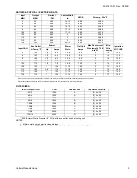
1. Airflow expressed in standard cubic feet per minute (CFM) and in cubic meters per minute (m
3
/min).
2. Return air is through side opposite motor (left side).
3. Airflows above 1800 CFM (50.97 m
3
/min) require either return from two sides or one side plus bottom.
4. Motor voltage at 115 V.
5. NR = Operation at this static pressure is not recommended.
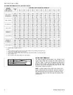
FILTER PERFORMANCE
The airflow capacity data published in the “Blower Perfor-
mance” table listed above represents blower performance
WITHOUT filters. To determine the approximate blower per-
formance of the system, apply the filter drop value for the fil-
ter being used or select an appropriate value from the “Filter
Performance” table shown below.
NOTE:
The filter pressure drop values in the “Filter Perfor-
mance” table shown below are typical values for the type of
filter listed and should only be used as a guideline. Actual
pressure drop ratings for each filter type vary between filter
manufacturer.
BLOWER PERFORMANCE CFM - (WITHOUT FILTER)
MODELS
Input/Output/
Airflow/cabinet
Speed
Tap
EXTERNAL STATIC PRESSURE, INCHES WC
0.1
0.2
0.3
0.4
0.5
0.6
0.7
0.8
0.9
1.0
cfm
cfm
cfm
cfm
cfm
cfm
cfm
cfm
cfm
cfm
40/32/1200/"A" †
60/48/1200/"A" †
80/64/1200/"A" †
HIGH 1580 1530 1470 1405 1330 1245 1150 1045 890 650
MED-HIGH
1110 1100
1075
1060
1030 980 920 835 680 520
MED-LOW
845 840 830 815 790 750 670 595 480 320
LOW 675 665 660 645 620 585 530 455 360 255
80/64/1600/"B" †
HIGH 1970 1935 1900 1850 1795 1735 1660 1590 1495 1395
MED 1445 1435 1425 1415 1405 1375 1350 1300 1240 1160
LOW 1245 1235 1225 1215 1205 1190 1170 1135 1090 995
100/80/1200/"B" †
HIGH 1675 1645 1595 1530 1465 1385 1280 1155 1025 810
MED 1270 1260 1250 1240 1215 1185 1125 1035 910 695
LOW 955 950 945 935 920 905 865 810 685 510
115/92/1600/"C"
HIGH 2040 1975 1925 1855 1780 1695 1610 1505 1380 1225
MED 1725 1685 1650 1610 1555 1500 1425 1340 1220 1075
LOW 1365 1355 1325 1290 1265 1250 1210 1140 1045 940
100/80/2000/"C" †
115/92/2000/"C" †
HIGH 2400 2320 2275 2200 2115 2025 1930 1825 1700 1570
MED 2050 2025 1980 1930 1855 1805 1720 1635 1530 1400
LOW 1690 1675 1660 1630 1610 1560 1500 1430 1330 1225
130/104/2000/"D" †
HIGH 2380 2330 2270 2205 2120 2025 1920 1815 1705 1565
MED 2040 2010 1980 1920 1875 1790 1705 1610 1515 1385
LOW 1690 1680 1655 1630 1590 1530 1490 1425 1350 1235
NOTE: Data below reflects airflows with two return openings - two sides or one side and bottom
80/64/2000/"C"
100/80/2000/"C" †
115/92/2000/“C" †
HIGH 2405 2340 2275 2210 2130 2050 1955 1840 1725 1600
MED 2005 1990 1965 1935 1880 1815 1725 1635 1535 1410
LOW 1655 1640 1625 1610 1585 1540 1485 1420 1340 1235
130/104/2000/"D" †
HIGH 2385 2335 2275 2195 2120 2040 1935 1820 1700 1555
MED 2005 1980 1955 1905 1845 1775 1700 1610 1500 1370
LOW 1640 1635 1620 1605 1575 1540 1480 1400 1330 1225
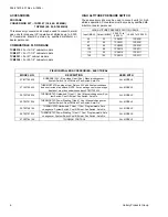
BLK
WHT
GRN
BLK (HOT)
WHT (NEUTRAL)
GRN
NOMINAL
120 VOLT


