5
2 - Installation (cont’d)
Table 2 - Display DIP switch settings
a : Factory settings.
2.6 - Mount thermostat
Caution
Always disconnect power supply and remove battery from the
thermostat before connecting the ribbon cables to prevent elec-
trical shock and equipment damage.
Use the Following procedure to connect the display ribbon
cables to the subbase.
1. Check that the 24 Vac power supply is disconnected.
2. Check that the 9 Vdc battery is not installed in the display.
Important : First be sure to connect the 12 pin ribbon cable to
the base.
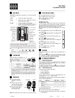
3. Connect the 12 pin (larger) ribbon cable to the display. See
Fig. 4.
4. Connect the 9 pin (smaller) ribbon cable to the display.
5. If using a 9 Vdc battery, go to the Install Battery backup sec-
tion for installation instructions.
2.7 - Install battery
The 9 volts battery is not necessary for the operation of the ther-
mostat, but holds the program during power outages. When the
power is restored, the system will resume normal operation.
Without the battery, the system will adopt the default setpoints.
Refer to the "technical data". Use the following steps to install a
battery :
1. Locate the battery holder on the back of the display.
2. Slide the battery up to the connector until it is firmly seated.
Notes : Observe the polarity when snapping a 9 volt alkaline bat-
tery into the holder.
The plugs must be firmly seated on the connectors for
the thermostat to work properly
3. Hang the top edge of the display on the subbase hooks. See
Fig. 5.
4. Swing down and press on the lower edge until the thermostat
snaps in place.
5. Insert and tighten three Allen head screws on the bottom of
the thermostat. See Fig. 5.
Switch
Setting
Function
1
ONa
°
F display
OFF
°
C display
2
ONa
12 hour clock display
OFF
24 hour clock display
ONa
Continuous fan operation in occupied
3
period
OFF
Intermittent fan operation in occupied
period
4
Non functional switch
ONa
Keyboard is used for programming
5
OFF
Keyboard disabled, but can be used
to review program, perform overrides
and make clock changes.
1
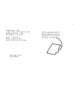
Fig. 5 - Ribbon cable and display monting


