YOKOHAMA ADMAG TI AXFA11G User Manual Download Page 30


<4.  Wiring>

29

IM 01E25A01-01EN

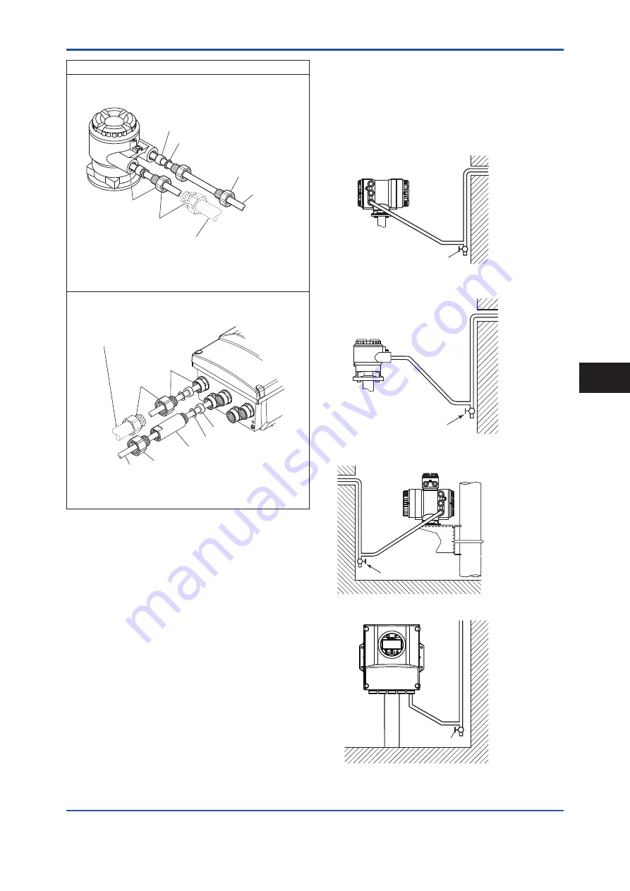
(4)  Waterproof Gland with JIS G3/4 Female

Remote Sensor

Optional code: EW

Gasket

Washer

*  When connecting G1/2, remove the conversion plug and

connect directly to electrical connection.

Cable

G3/4

G1/2

Conversion plug (x2)*

F0416.ai

When working on conduit or flexible tube (G3/4)

Remote Transmitter (AXG1A/AXFA11)

Optional code: EW5 (AXG1A), EW (AXFA11)

Gasket

Washer

*  When connecting G1/2, remove the conversion plug

and connect directly to electrical connection.

When working on conduit or 

flexible tube (G3/4)

Extension plug (x2)

Cable

G3/4

G1/2

Conversion plug (x5)*

F0417.ai

4.3.2  Conduit Wiring

When wiring the conduits, utilize the waterproof gland to 

prevent water from flowing in through the conduit. Place 

the conduit pipe on an angle as shown in the following 

figures.

Install a drain valve at the low end of the vertical pipe, and 

open the valve regularly.

F0418.ai

Drain valve

Figure 4.3.1  Integral Flowmeter

Drain valve

F0419.ai

Figure 4.3.2  Remote Sensor

F0420.ai

Drain valve

Figure 4.3.3  Remote Transmitter (AXW4A)

F0421.ai

Drain valve

Figure 4.3.4  Remote Transmitter (AXG1A/AXFA11)

W

iring

4

Summary of Contents for ADMAG TI AXFA11G

Page 1: ...smitter 30 4 5 Connecting to Remote Sensor and Remote Transmitter Sensor Side 36 4 6 Input and Output 39 5 Basic Operating Procedures 5 1 Operation by Display unit 42 5 2 Display and Basic Configuration 42 5 3 Display Mode and Setting Mode 45 5 4 Parameter Setting from Display Panel 46 5 5 microSD Card Setting 48 5 6 BRAIN Configuration Tool 48 5 7 HART Configuration Tool 49 5 8 Modbus Configurati...

Page 2: ...Flowmeter HART Communication Type IM 01E21A02 02EN ADMAG TI Series AXG AXW Magnetic Flowmeter Modbus Communication Type IM 01E21A02 05EN ADMAG TI Series AXG AXW Magnetic Flowmeter FOUNDATION Fieldbus Communication Type IM01E21A02 03EN ADMAG TI Series AXG1A Magnetic Flowmeter BRAIN Communication Type IM 01E22C02 01EN ADMAG TI Series AXG1A Magnetic Flowmeter HART Communication Type IM 01E22C02 02EN ...

Page 3: ...ent YOKOGAWA will not be liable for malfunctions or damage resulting from any modification made to this instrument by the customer The instrument should be disposed of in accordance with local and national legislation regulations Regarding This User s Manual This manual should be provided to the end user The contents of this manual are subject to change without prior notice All rights reserved No ...

Page 4: ...oid long term continuous operation at relative humidity above 95 WARNING Purpose of use This instrument is the Magnetic Flowmeter for use of measuring the liquid flow Do not use this instrument for other purposes WARNING Installation wiring and maintenance of the magnetic flowmeter must be performed by expert engineer or skilled personnel No operator shall be permitted to perform procedures relati...

Page 5: ...om electrical motors transformers and other power sources in order to avoid interference with measurement WARNING Install an external switch or circuit breaker as a means to turn the power off capacitance 15A conforming to IEC60947 1 and IEC60947 3 Locate this switch either near the instrument or in other places facilitating easy operation Affix a Power Off Equipment label to this external switch ...

Page 6: ...the power Power Supply Code 1 AC Type Rated Power Supply 100 to 240 V AC 50 60 Hz DC Type Rated Power Supply 100 to 120 V DC Power Supply Code 2 AC Type Rated Power Supply 24 V AC 50 60 Hz DC Type Rated Power Supply 24 V DC Power Consumption Integral Type 13 W Remote Type with AXG4A 13 W Remote Type with AXG1A 32 W Note Power Consumption is independent of communication and I O specification Note F...

Page 7: ...r due to improper maintenance of the installation location Failure or damage due to modification or repair by any party except YOKOGAWA or an approved representative of YOKOGAWA Malfunction or damage from improper relocation of the product in question after delivery Reason of force majeure such as fires earthquakes storms floods thunder lightening or other natural disasters or disturbances riots w...

Page 8: ... above 1 pc 2 1 Model and Specifications Check As shown in Figure 2 1 to Figure 2 5 the model suffix code serial number meter factor fluid specification and device information are found on the name plate located on the outside of the housing And this instrument can check their information from parameters Read the user s manual of applicable communication type as listed in Table 1 1 for checking de...

Page 9: ...torage location that fulfils the following conditions A place where it will not be exposed to rain or water A place subject to minimal vibrations or shocks Temperature and humidity levels should be as follows Temperature 10 to 70 C Humidity 5 to 80 RH no condensation The preferred ambient temperature and humidity levels are 25 C and approximately 65 RH If the instrument is transferred to the insta...

Page 10: ...alling the instrument in a place subject to shocks or vibrations 3 1 Piping Design Precautions IMPORTANT Design piping correctly referring to the following to prevent damage to sensors and to assure accurate measuring NOTE This section describes the remote sensor as an example The same attention must be paid to the integral flowmeter 1 Location IMPORTANT Install the flowmeter in a location where i...

Page 11: ...raight pipe section where the upstream part is sufficiently rectified 4 Maintaining Stable Fluid Conductivity IMPORTANT Do not install the flowmeter where fluid conductivity tends to become uneven If chemicals are fed near the upstream side of a magnetic flowmeter they may affect the flow rate s indications To avoid this situation it is recommended that the chemical feed ports be located on the do...

Page 12: ...the top to ensure that the pipes remain fully filled h h 0 h 0 h F0306 ai Incorrect Correct Incorrect Correct Figure 3 1 4 Mounting Positions Avoid air bubbles IMPORTANT If air bubbles enter a measurement pipe flow rate indications may be affected and measurement errors may be caused In cases where fluids contain air bubbles piping must be designed to prevent them from accumulating in the measurem...

Page 13: ...owmeter or expose it to excessive shock In particular be careful not to subject the flange surface to shock This may lead to lining damage which will result in inaccurate readings 3 Flange Protection Covers IMPORTANT Keep the protective covering i e the corrugated cardboard or other cushioning material in place over the flange except when mounting the flowmeter to the pipe 4 Terminal Box Cover IMP...

Page 14: ... placed between each the grounding ring and the sensor to avoid fluid leakage These gaskets are to be supplied by customer Do not forget those gaskets also when ordering and attaching the grounding rings later additionally Use the gasket of the equivalent hardness for gasket customer pipe and gasket sensor NOTE The tightening torque of gaskets varies by the type and external dimensions of the lini...

Page 15: ... flowmeter In addition adjust any misalignment when the magnetic flowmeter is brought in as the jack can adjust vertical position but not horizontal one 4 Applying Gasket and optional Grounding Rings Gasket Necessary gaskets for piping connection are as below depending on the choice of grounding rings Use sheet gaskets designed to fit for the flange ratings ad fluid specifications The GF type 1 ga...

Page 16: ...wmeter Set the angle of both handles symmetrically to be 45 degree from top If there are any bolt holes under the handles turn the grounding rings clockwise in order to locate handles between bolt holes Center the grounding ring to the center of the magnetic flowmeter 4 Connect the wire from the grounding ring to the screw of the magnetic flowmeter s flange and fix the wire by the nut This procedu...

Page 17: ...or sizes 1100 mm 44 in and above Mounting Procedure with optional Grounding Rings GR2 The grounding rings are installed and locked onto the magnetic flowmeter with gaskets B when shipped from factory Install the magnetic flowmeter into the customer s pipe with gaskets A supplied by customer 5 Tightening Nuts Pass the bolts from pipe line side not magnetic flowmeter side and tighten the nuts accord...

Page 18: ...nection Size mm inch ASME B16 5 500 600 B16 47 700 1000 Class 150 EN1092 1 PN10 JIS B2220 10K EN 1092 1 PN16 AWWA C207 Class D AS2129 Table D E AS4087 PN16 JIS F12 JIS 75M 500 20 71 to 118 60 to 99 74 to 123 76 to 123 131 to 218 600 24 97 to 162 82 to 126 101 to 168 118 to 171 124 to 206 700 28 125 to 208 135 to 202 146 to 244 120 to 200 167 to 242 202 to 337 800 32 176 to 294 160 to 229 190 to 31...

Page 19: ...700 1000 Class 150 EN1092 1 PN10 JIS B2220 10K EN 1092 1 PN16 AWWA C207 Class D AS2129 Table D E AS4087 PN16 JIS F12 JIS 75M 500 20 626 to 1044 527 to 876 652 to 1087 674 to 1089 1159 to 1931 600 24 862 to 1436 727 to 1113 894 to 1490 1043 to 1512 1095 to 1825 700 28 1106 to 1843 1193 to 1791 1295 to 2159 1061 to 1769 1478 to 2142 1788 to 2980 800 32 1562 to 2603 1420 to 2024 1680 to 2800 1494 to ...

Page 20: ... Screw U bolt Figure 3 4 1 2 inch Pipe Vertical Mounting 1 Fix the instrument on the mounting fixture using four screws 2 Fix the mounting fixture with the instrument installed on a 2 inch pipe using a U bolt Horizontal Pipe Mounting F0318 ai Mounting fixture 2 inch pipe Nut U bolt Washer Screw Figure 3 4 2 2 inch Pipe Horizontal Mounting 1 Fix the instrument on the mounting fixture using four scr...

Page 21: ...smitter AXFA11 Remote Transmitter can be mounted using surface mounting 2 inch pipe mounting or panel mounting by the same process of AXG1A Please refer 3 4 3 for the process IMPORTANT Mounting fixture on equipment intended to be mounted on a wall or ceiling shall withstand a force of four times the weight of the equipment AXFA11 3 4 kg 7 5 lb 3 5 Changing Direction of Electrical Connection 3 5 1 ...

Page 22: ...ed direction of electrical connection after delivery Submersible Type Model AXW W For District Heating and Cooling or Condensation proof Optional code DHC 1 The following tools are required Hexagonal wrench nominal size 1 5 Spanner nominal size 46 2 Turn off the power to the flowmeter 3 Using the spanner loosen the hexagonal nuts at the neck of remote sensor F0325 ai 4 Using the hexagonal wrench l...

Page 23: ...Sensor CAUTION Do not loosen the screw at the opposite side of electrical connection see the figure below F0328 ai 4 Rotate the transmitter or the terminal box in the desired direction The direction can be changed to 90 degrees 90 degrees or 180 degrees NOTE The terminal box can be rotated 90 degrees to 180 degrees at every 90 degrees from the arrow mark indicating the flow direction Do not exceed...

Page 24: ...irection 90 degrees Hold the display unit with your hand and loosen the two mounting screws Rotate the display unit 90 degrees clockwise and confirm the assembling position taking care of the connector and wire of the display unit At this time do not remove the connector Secure the display unit using its two mounting screws F0332 ai Clockwise 90 degrees Mounting screw two screws Figure 3 6 3 Chang...

Page 25: ... remote type ground the remote sensor and the transmitter separately Terminate all the cable finish with crimp terminal of a round or rod shape depending on the shape of the terminal block and connect them reliably Always route the power and output signal cables in separate steel conduit tubes except when the power supply voltage is 24 V and four core cables are used for wiring For the remote type...

Page 26: ...5 3 35 EX1 EX2 EX1 EX2 85 3 35 On the sensor side Unit mm approx inch F0401 ai Crimp terminal Figure 4 2 1 Cable Finish for Excitaiton Cable NOTE For excitation cable and power cable always use a crimp terminal with an insulation cover Use crimp tools supplied by the manufacturer of the crimp terminal you want to use to connect the crimp terminal and cable Use crimp tools that are appropriate for ...

Page 27: ...strument is of watertight construction as stipulated in JIS C 0920 It is shipped with a wiring bracket waterproof gland waterproof gland with union or a plastic gland attached only in cases where an optional specification is selected for the electrical connection Cable gland has the following kinds depending on the type and size Integral Type Flowmeter AXW Size 500 to 1000 mm 20 to 40 in Optional ...

Page 28: ...waterproof glands are recommended Do not over tighten the glands or damage to the cables may result Tightness of the gland can be checked by confirming that the cable is held firmly in place For working on the conduit or the flexible tubes G1 2 remove the waterproof gland and attach them directly to the electrical connection 1 Waterproof Gland Integral Flowmeter Optional code EG2 EG3 Cable Waterpr...

Page 29: ...mote Transmitter AXW4A Optional code EU4 EU5 Gasket Washer Tightening gland When working on conduit or flexible tube G1 2 only Cable G1 2 F0411 ai Remote Transmitter AXG1A AXFA11 Optional code EU5 AXG1A EU AXFA11 Gasket Washer Tightening gland When working on conduit or flexible tube G1 2 only Cable G1 2 F0412 ai 3 Plastic Gland Integral Flowmeter Optional code EP2 EP3 Plastic gland Gasket F0413 a...

Page 30: ...o electrical connection When working on conduit or flexible tube G3 4 Extension plug x2 Cable G3 4 G1 2 Conversion plug x5 F0417 ai 4 3 2 Conduit Wiring When wiring the conduits utilize the waterproof gland to prevent water from flowing in through the conduit Place the conduit pipe on an angle as shown in the following figures Install a drain valve at the low end of the vertical pipe and open the ...

Page 31: ... to IEC60947 1 and IEC60947 3 Locate this switch either near the instrument or in other places facilitating easy operation Affix a Power Off Equipment label to this external switch or circuit breaker Wiring Procedure 1 Check the instrument s power is off then remove the terminal cover transparent 2 Wire the power supply cable and the functional grounding cable to the power supply terminals 3 Insta...

Page 32: ...or smaller power consumption 20 W 28 8 Allowable Cable length m ft Usable voltage range V F0424 ai Figure 4 4 3 Supply Voltage and Power Supply Cable Length AXG1A Remote Transmitter 3 Setting Power Supply Frequency IMPORTANT Upon shipment from the manufacturing plant the local commercial power frequency is set to 49 Hz and power synchronization is set to asynchronization Do not change the followin...

Page 33: ...optional code F0428 ai Grounding Resistance 10 Ω or less Class C requirements Note When lightning protection performance by the built in lightning protectors is not required grounding resistance 100 Ω or less Class D requirements can be applied 600 V vinyl insulated cable Cable cross section area 2 mm2 and cross section area larger than power cable F0429 ai In case grounding rings are used In case...

Page 34: ... the flowmeter by turning it clockwise Tighten the cover locking screw 1 and 3 See Figure 4 4 5 and Figure 4 4 6 counterclockwise using a hexagonal wrench nominal size 3 to lock the cover 2 Terminal Configuration Integral Flowmeter and AXW4A Transmitter F0432 ai M4 Screw Type Integral Type AXW4A Remote Transmitter To be wired to Power Supply and I Os Clamp Type Terminal Symbol N L I O4 I O4 I O3 I...

Page 35: ... and I O code Connection Terminal Fieldbus I O1 I O2 I O3 I O4 F Fieldbus Passive P Sout Passive Iout1 Current output with BRAIN HART communication Iout2 Current output without BRAIN HART communication P Sout1 Pulse output or status output P Sout2 Pulse output or status output Sin Status input Modbus Modbus communication Fieldbus FOUNDATION fieldbus communication The position of Converter Communic...

Page 36: ...ART communication Iout2 Current output Iin Current input P Sout1 Pulse output or status output P Sout2 Pulse output or status output Si11 Si12 Status input Two inputs So11 So12 Status output Two outputs The position of Communication and I O code Remote Transmitter AXG1A G000 1 IMPORTANT Do not wire the terminal without terminal symbols in terminal layout labels 3 Installing the Cover While support...

Page 37: ...layout labels 3 Installing the Cover While supporting the front of the cover with your hand flip the connecting screw protective cover over and tighten the four connecting screws 4 5 Connecting to Remote Sensor and Remote Transmitter Sensor Side WARNING Before wiring be sure that the power supply to magnetic flowmeter has been turned off to prevent an electrical shock 1 Removing the Cover Loosen t...

Page 38: ...Diagram AXW4A Remote Transmitter 2 Connection with AXG1A Remote Transmitter Connect wiring as shown in the figure below AXG1A transmitter Transmitter Remote sensor F0443 ai SA A B SB C EX1 EX2 Taping A B Taping C EX1 EX2 Individually tape and insulate the shields corresponding to SA and SB on the remote sensor side Remote sensor EX2 EX1 A B C AXFC dedicated signal cable Excitation cable Figure 4 5...

Page 39: ...ence electric potentials terminal potential of the sensor and the transmitter the measuring fluid potential and the ground potential and then reduce the affection by noise The grounding rings make a connection between the measured fluid and the ground and protects the flared face of lining Grounding rings are supplied with the instruments when specified with dedicated optional code Grounding Resis...

Page 40: ...Active current output lout Active pulse output P Sout Connection of an electronic counter Observe that maximum allowable voltage and voltage polarity are correct when wiring Load resistance 1 kΩ or more Internal power supply 24 V DC 20 Maximum pulse rate 10 000 pulses s Maximum frequency output rate 12 500 Hz P Sout 24 V Transmitter 0 V P Sout Electronic Counter Load Resistance F0447 ai Figure 4 6...

Page 41: ...iter observe that maximum allowable current voltage polarity and output current level are correct Load resistance External instruments 1 kΩ or more Internal power supply 24 V DC 20 P Sout 24 V Transmitter 0 V P Sout Load Resistance F0451 ai Figure 4 6 6 Connection diagram Active status output P Sout Passive status output P Sout or Sout So11 or So12 ALM Because of connecting to a transisiter observ...

Page 42: ...nal without voltage Loading voltage during the switching status Close may result in damage on the electrical circuit The status input is used for connecting to the following no voltage contacts Switching status Resistance Closed 200 Ω or less Open 100 kΩ or more Transmitter Sin Sin F0454 ai Figure 4 6 9 Connection diagram Status input Sin Wiring 4 ...

Page 43: ...eep the cover closed and operate the setting switches from the outside of the glass window If dirt dust or other substances surfaces on the glass of display cover wipe them clean with a soft dry cloth The operation with dirty gloves may cause a switch response error NOTE The language on the display is set to English as default at the factory shipment Select the adequate language referring to the S...

Page 44: ... 2 Explanation of display example F0502 ai Device address Baud rate Transmission mode R RTU A ASCII Stop bit 1 1 bit 2 2 bit Parity N None O Odd E Even Example R 001 19200 E 1 5 2 2 Basic Configuration for Display For paramter setting from display panel configurable parameters differ by the three operational levels specfied in Table 5 2 2 and a passcode is needed to enter into Setting mode No pass...

Page 45: ...e F0506 ai 0 50000 50 0 12 00 m s mA 00 00 VEL FLP AO1 SET SFT INC F0511 ai 00 00 FNL SET SFT INC Normal Long tag 1234567 TAG12345 LTG TAG Indicate 32 characters of the Long Tag in the first line Indicate 16 characters in the first half of 32 characters of the Long Tag in the second and third lines 4 line F0507 ai 0 50000 50 0 12 000 m s mA Normal 00 00 VEL AO1 FNL SET SFT INC FLP F0512 ai 00 00 F...

Page 46: ...y shipment is set to 0000 F0519 ai Pass code 0000 0000 9999 00 00 SET SFT INC 8 When the Operation Level is determined the screen moves to Device setup as the Setting Mode where parameters can be configured 9 After completing parameter setting push ESC switch The screen returns to the Display Mode NOTE In the case of Ind soft rev follow the procedure bellow Communication Ind soft rev HART BRAIN Mo...

Page 47: ...T 1234 00 00 SET SFT INC Configure the data with a combination of alphanumeric characters Tag No Special unit etc The alphanumeric type indicates alphanumeric characters in the following order 0123456789ABCDEFGHIJKLMNOPQRSTUVWXYZabcdefghijklmnopqrstu vwxyz _ space 5 4 Parameter Setting from Display Panel This section explains how to specify the parameters from display panel Select Specialist at th...

Page 48: ...to the unit change 5 4 2 Setting example of Numeric type Data Flow rate span The following is the procedure of changing the Flow rate span as Numeric type parameter Display Menu Path Device setup Detailed setup Pro var Volume Span NOTE Be sure to set the Flow rate unit in the beginning when the Flow rate unit and Flow span value are changed at the same time When the unit is changed the value of fl...

Page 49: ...gement Wizard is shown as below Read the user s manual of BT200 IM 01C00A11 01E for the operation and the user s manual of BRAIN communication type as listed in Table 1 1 for the detailed parameter setting via BRAIN communication The communication signal is superimposed onto the 4 to 20 mA DC analog signal to be transmitted The BRAIN configuration tool can interface with this device from the contr...

Page 50: ... output signal It is recommended to set a low pass filter approximately 0 1s to the receiver in order to reduce the output effect from communication signal Before online communication confirm that communication signal does not give effect on the upper system 5 7 2 HART Configuration Tool and DeviceRevision IMPORTANT Protocol revision supported by HART configuration tool must be the same protocol r...

Page 51: ... Read the user s manual of Modbus communication type as listed in Table 1 1 for the detailed parameter setting via Modbus communication 5 8 1 Connections with Modbus Configuration Tool The Modbus configuration tool is connected to the transmitter instead of Modbus host RS 485 USB Adaptor is required to connect transmitter to PC See Figure 5 8 e g FieldMate Pull Up Pull Down Slave n ADMAG LT LT Bal...

Page 52: ...t have the DD or capabilities files you can download them from our web page http www yokogawa com fld The device revision is as follows DD Revision 1 or later Device Type AXG4A 0x0016 AXW4A 0x0017 Device Revision 1 Read 5 7 2 HART Configuration Tool and Device Revision for the confirmation of DD revision 2 Device Type Manager DTM and Device Revision When configuring the parameters by FieldMate use...

Page 53: ...ocity is completely zero by closing the valve Each time that the fluid being measured is changed be sure to carry out zero adjustment with the new fluid 6 2 Zero Adjustment from Display Unit A procedure of executing zero adjustment is as follows Display Menu Path Device setup Diag Service Autozero Execute Device setup Diag Service Autozero Result Zero value Enter the Setting Mode Read Section 5 3 ...

Page 54: ...rve the safety do not touch the electrical circuit and the cables except the setting switches When installing the cover in order to contact the housing and the cover be sure to screw it firmly into the housing without any space between them 1 Remove the cover 2 While holding the display by hand loosen the two mounting screws 3 While holding the display by hand careful for connecting cable set the ...

Page 55: ...ved from the transducer block It is possible to conduct testing for the downstream function blocks or alarm processes A SIMULATE_ENABLE switch is mounted in the transmitter amplifier This is to prevent the accidental operation of this function When this is switched on simulation is enabled See table below To initiate the same action from a remote terminal if REMOTE LOOP TEST SWITCH is written to t...

Page 56: ...set to 1 the resulting the device address is 64 1 26 0 25 0 24 0 23 0 22 0 21 0 20 Setting of Line Termination Switch SW2 This switch is only available for the product with Modbus communication Line terminations of two ends on the bus are required to communicate Modbus One termination mode can be set using the line termination switch SW2 See Figure 6 3 1 Table 6 3 4 Line termination switch SW2 Pos...

Page 57: ...in cases where the optional codes C1 or C2 have been specified the output direction will be set to Low i e 2 4 mA Modification of the burnout direction must be carried out using the burnout switch i e Switch 1 1 See Figure 6 3 4 Table 6 3 6 Burnout switch Switch 1 1 Position of Switch Burnout Direction Burnout Output Description 1 2 ON L OFF H High 21 6 mA When optional code C1 or C2 is not specif...

Page 58: ...n making switch settings 1 Setting of Burnout Switch The burnout function sets the direction of current output in situations where the CPU has become damaged Upon shipment from the manufacturing plant the burnout direction is set to High i e 25 mA however in cases where the optional codes C1 have been specified the output direction will be set to Low i e 0 mA Modification of the burnout direction ...

Page 59: ...d Contact Yokogawa service center F 022 PWM 2 stop Error of pulse width modulation 2 was detected Contact Yokogawa service center F 023 Opt bd mismatch Mismatch of option board was detected Contact Yokogawa service center F 024 Opt bd EEP FAIL Failure of EEPROM option board was detected Contact Yokogawa service center F 025 Opt bd A D FAIL Failure of A D option board was detected Contact Yokogawa ...

Page 60: ...ccurred Check the AI2 Output Value AI2 OUT VALUE and configuration of AI2 Lo Lo Lim AI2 LO_LO_LIM AI2 Lo Lo Pri AI2 LO_LO_PRI N 370 AI2 Hi Alarm High Alarm has occurred Check the AI2 Output Value AI2 OUT VALUE and configuration of AI2 Hi Lim AI2 HI_LIM AI2 Hi Pri AI2 HI_PRI N 371 AI2 Lo Alarm Low Alarm has occurred Check the AI2 Output Value AI2 OUT VALUE and configuration of AI2 Lo Lim AI2 LO_LIM...

Page 61: ...an mode Change the AI1 Block Mode Target AI1 MODE_BLK Target to Auto or other mode C 302 AI1 Not Schedule AI1 Block is not scheduled ScheduleAI1 Block C 303 AI1 Simulate Act AI1 block is in simulation mode Change the AI1 Simulation En Disable AI1 SIMULATE SIMULATE_ ENABLE to Disabled C 304 AI2 O S Mode AI2 Block is in O S mode Change the AI2 Block Mode Target AI2 MODE_BLK Target to Auto or other m...

Page 62: ...K Target to Auto or other mode C 349 DI3 Man Mode DI3 Block is in Man mode Change the DI3 Block Mode Target DI3 MODE_BLK Target to Auto or other mode C 350 DI3 Not Schedule DI3 Block is not scheduled ScheduleDI3 Block C 351 DI3 Simulate Act DI3 block is in simulation mode Change the DI3 Simulation En Disable DI3 SIMULATE SIMULATE_ ENABLE to Disabled C 352 AR O S Mode AR Block is in O S mode Change...

Page 63: ...t mode or not S 098 Pls 1 fix It was detected that fixied value is set to Pulse output 1 Check pulse output 1 is test mode or not S 099 Pls 2 fix It was detected that fixied value is set to Pulse output 2 Check pulse output 2 is test mode or not S 100 AI fix It was detected that fixied value is set to Current input Check current input is test mode or not C 101 Param restore run Restore function of...

Page 64: ...setting for Modbus communication type Revise the table of error messages 3rd July 2019 Front page 1 2 3 7 6 8 10 to 16 21 19 21 25 25 to 28 30 33 34 36 38 41 42 44 47 48 51 52 55 to 59 Change to style 2 Add AXG1A Add AXG1A Add Fieldbus to Trademarks Add EN number to 1 Add Fieldbus to 2 Add AXG1A to Table 1 2 Add AXG1A Revise figures of Remote converter Add AXG1A to 3 4 3 Revise figures of Remote c...

Reviews: