8-5
IM 01C50C05-01EN
F0803-5.ai
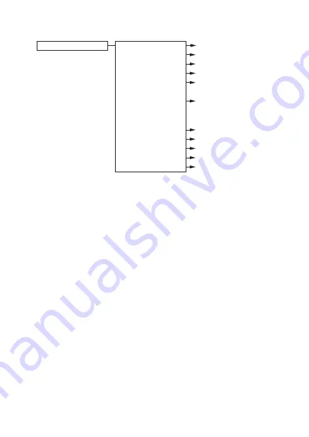
Setup
HART
Variable mapping
Range Variables
Process Sensor
Sensor 1 Setup
Sensor 2 Setup
Electronics/CJC Setup
Average Setup
Difference Setup
Trend Setup
Burst Setup
Trim Setup
Signal Condition
Output Condition
D1
D1
D1
D1
D2
Future use
D2
Future use
Future use
D2
D3
D4
D5
D6
D


