

<Toc> <Ind>
7-1
TI 05C01E02-01E
1st Edition : Oct. 31, 2001-00
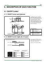
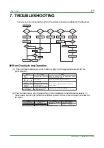
7. TROUBLESHOOTING
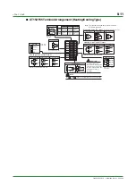
In the event of an abnormality, perform the following checks as outlined by the flowchart.
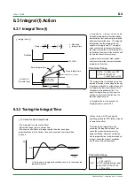
Is the controller defective?
Completely inactive?
Normal?
Contact us for repair
Problem solved
Cancel the setting
Key operation failure?
Is the key
locked?
Communication
function included?
No communication capability
Normal?
Correct it
Check the terminal connection
of the power supply
Check key-lock
setting
Display failure?
I/O signal failure?
Communication
failure?
Turn the power off,
then on
Check the communication-
related parameters
Verify the spec. of
communicating partner
Check the
communication wiring
Verify the I/O spec.
of controller
Verify the spec. of
I/O destinations
Check the model
and suffix codes
Check the power
supply voltage
Yes
Yes
Yes
Yes
Yes
Yes
Yes
Yes
Yes
No
No
No
No
No
No
No
No
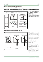
■
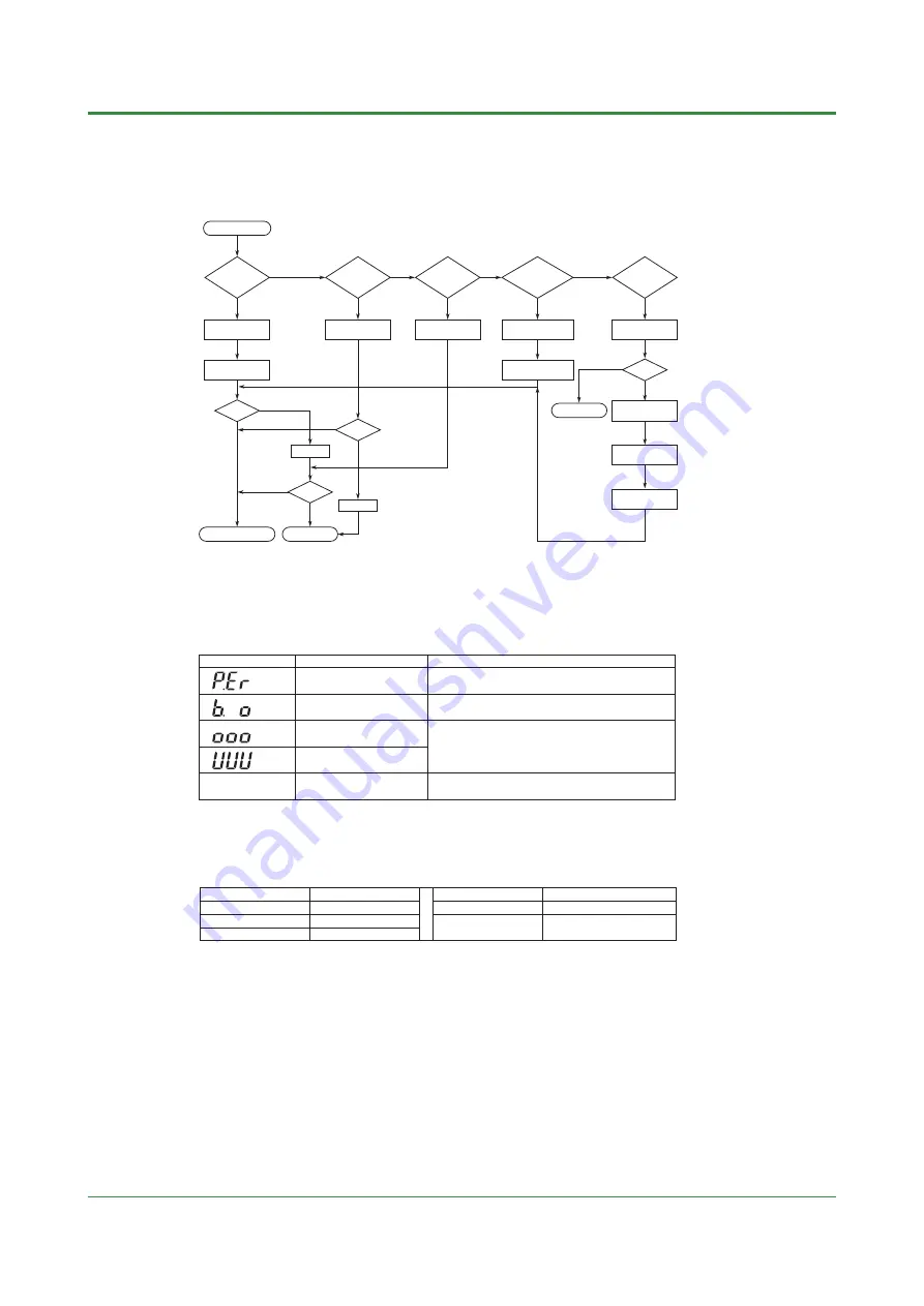
Error Display during Operation
(1) If the controller displays one of the following, carry out the appropriate remedy for the
particularerror.
Display
Error content
Remedy
P.Er
Flashing period
on PV display
The parameter is abnormal Check the settings of all the parameters and set
them at their proper values.
B.o
Input burnout
Check the sensor wiring and correct it.
OOO
PV over-scale
(PV exceeds its effective range.) Check the input type and range settings and
correct them.
Press any key to stop the flashing.
UUU
PV under-scale
(PV falls below its effective range.)
Communication failure
(for /RS option only)
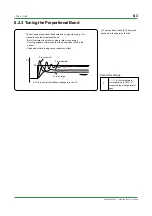
(2) The controller needs to be repaired if any of the indications in the table below appear. In
these cases, do not try to repair the controller yourself. Order a new controller or contact us
for repair.
Display
Unknown (at power-on)
All extinguished (at power-on)
Err (at power-on)
Error content
CPU failure
Power source failure
Calibration abnormal
Display
Flashing Err (at power-on)
Flashing Err
(during operation)
Error content
RAM or ROM failure
A/D converter failure,
RJC failure, or EEPROM failure
Summary of Contents for UT130
Page 2: ...Blank Page ...
Page 4: ...Blank Page ...
Page 8: ...Blank Page ...
Page 30: ...Blank Page ...
Page 48: ...Blank Page ...
Page 60: ...Blank Page ...
Page 72: ...Blank Page ...


