

<Toc> <Ind>
4-3
TI 05C01E02-01E
1st Edition : Oct. 31, 2001-00
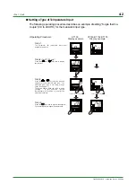
●
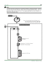
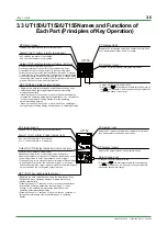
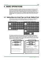
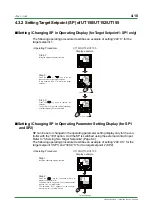
Setting a Voltage Input Type and Display Scale (for UT150/UT152/UT155
only)
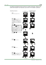
The following operating procedure describes an example of setting “1 to 5V DC voltage
input signals” for the measured input type, and “0.0 to 500.0” for the display scale.
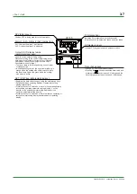
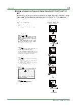
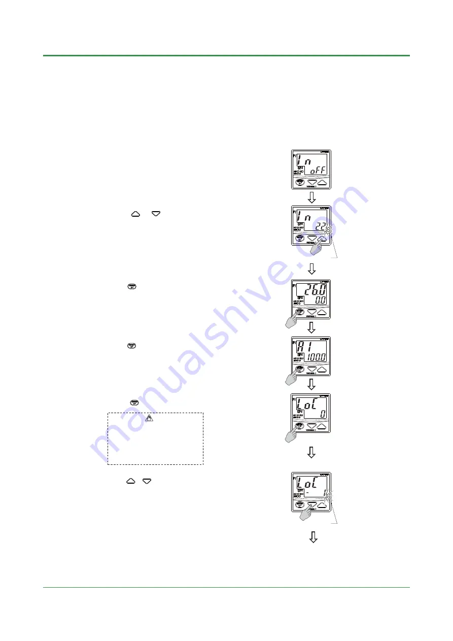
Step 1:
The parameter "IN" (measured input type)
appears at power on.
UT150/UT152/UT155
Display example
Flashes during change.
Step 2:
Press the or key to set the required
setpoint for the measured input type. The
measured input type is set using a range code.
(See Page 4-1)
The period flashes while the value is being
changed. In this example, "1 to 5V DC" (setpoint:
22) is set for the measured input type.
To the next page
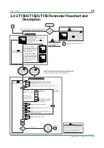
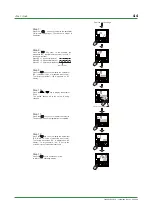
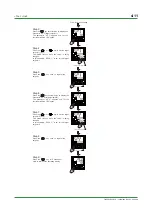
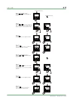
Step 4:
Press the key for 3 seconds or more to display
the parameter "A1".
The parameter "A1" appears only for the controller
with the "/AL" or" /HBA" option.
The parameter "CTL" appears for the controller
without the "/AL" or" /HBA" option.
Step 3:
Press the key once to register the setpoint. The
operating display appears automatically.
The Step 4 onwards describes the procedure to set a
display scale. The display scale is changed from "0.0
to 100.0 "(factory-set default) to "0.0 to 500.0".
Step 5:
Press the key several times to display the
parameter "LOC."
Set "-1" to enter the setup parameter
setting display. But if "LOC" = 1 or 2 is
already set, the parameter value can not
be changed by setting "LOC" = -1 only. To
change the parameter value, set "LOC" = 0
at first (for disabling key lock), then set
"LOC" = -1 once again
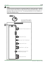
NOTE
Step 6:
Press the or key to display "-1."
Flashes during change.
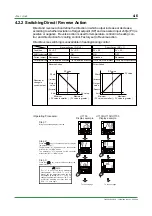
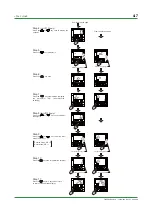
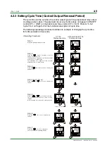
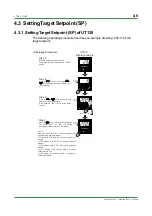
<Operating Procedure>
Summary of Contents for UT130
Page 2: ...Blank Page ...
Page 4: ...Blank Page ...
Page 8: ...Blank Page ...
Page 30: ...Blank Page ...
Page 48: ...Blank Page ...
Page 60: ...Blank Page ...
Page 72: ...Blank Page ...


