YOKOGAWA mR10000 436101 User Manual Download Page 36

36

IM 04P01B01-02E

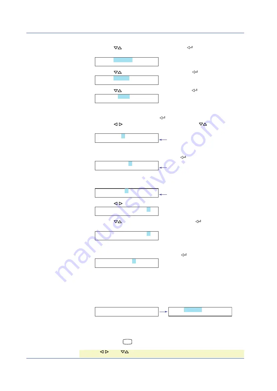
Selecting the Input Type

5.

Press the 

 key to select 

Scale

, and press the 

 key (for the selectable

settings, see “Explanation” on page 37).

Mode=Scale
Scales and record

6.

Press the 

 key to select 

Volt

 and then press the 

 key.

Type=Volt
DC Voltage

7.

Press the 

 key to select 

20V

 and then press the 

 key.

Range=20V
20mV-50V

Setting Span Left

8.

Set Span_L to 

0.00

, and press the 

 key.

Press the 

 key to select the desired digit. Press the 

 key to select the

value.

Span_L=   0.00
 -20.00/  20.00V

Displays the range of Span_L.

Setting Span Right

9.

Likewise, set Span_R to 

10.00

, and press the 

 key.

Span_R=  10.00
 -20.00/  20.00V

Displays the range of Span_R.

Setting the Decimal Position and Scale Left

10.

Display Scale_L.

Scale_L=   0.00
-200.00/ 300.00

Displays the scaling range.

11.

Press the 

 key to select the desired digit.

Scale_L=   0.00
-200.00/ 300.00

12.

Press the 

 key to select space and then press the 

 key (Scale_L is set to

0.0

).

Scale_L=   0.0
-200.00/ 300.00

Setting Scale Right

13.

Likewise, set Scale_R to 

400.0

, and press the 

 key.

Scale_R=  400.0
-2000.0/ 3000.0

The 

Setting complete

 screen is displayed. When this screen is displayed, the

settings entered up to then are applied.

Finishing the Settings

14.

When the 

Setting complete

 screen is displayed, press the 

ESC

 key.

The 

Set=Range

 screen is displayed.

04-04 Channel
Setting complete

Set=Range
Input range and

Setting the Unit and Finishing the Unit Settings

See steps 13 to 16 in Setup Example (2).

15.

Hold down the 

MENU

 key for 3 seconds to return to Operation mode.

Setting the Input Range and Alarm on Measurement Channels

*  When the          key or         key is pressed while holding down the 

SHIFT

 key, the operation is 

  reversed as when the respective key is pressed by itself.

Summary of Contents for mR10000 436101

Page 1: ...Operation Guide Yokogawa Electric Corporation IM 04P01B01 02E 4th Edition Models 436101 436102 436103 436104 436106 R10000 Recorder 4 P 1 B 1 0 2 E 0 4...

Page 2: ...ime 31 Setting the Input Range and Alarm on Measurement Channels 32 Setup Example 1 of Thermocouple Input 32 Setup Example 2 of 1 5V Input and unit 33 Setup Example 3 of 0 to 10 V Input and Unit 35 Se...

Page 3: ...ses of operation Safety Standards and EMC Standards This recorder conforms to IEC safety class I provided with terminal for protective grounding Installation Category II Measurement category II CAT II...

Page 4: ...e Software YOKOGAWA makes no warranties regarding the software accompanying this product except those stated in the WARRANTY that is provided separately Use the software on a single PC You must purcha...

Page 5: ...R Portable type Power cord AS st d7 H5J Portable type Power cord BS st d7 H5H Portable type Power cord GB st d7 M1 Mathematical function N1 Cu10 Cu25 RTD input N2 3 legs isolated RTD4 5 N3 Expansion i...

Page 6: ...W 1 1 1 1 1 1 1 2 1 1 1 1 1 1 B9901AX B9902AM B9902AN B9902AP B9902AQ B9902AR B9900BX 415920 415921 415922 438920 438921 438922 Note Quantity Model Ribbon cassette Plotter pen Mounting bracket Shunt r...

Page 7: ...m Changed Users with the same user name cannot be registered Added Language support German and French Added Calibration Correction Added Portable type Added 24 VDC AC power supply operation Added Cust...

Page 8: ...ages Also the recorder settings can be printed Internal Light A light is provided for easier viewing of the recording area of the chart paper Display Measured values can be displayed numerically or us...

Page 9: ...display and key panel It lights up the recording area of the chart paper Recording pen Records the measured value Plotter pen Prints various types of information Printer carriage Records measured valu...

Page 10: ...y while holding down the SHIFT key to switch the character type in reverse order UP DOWN Key Switches the setup item or the value Press this key while holding down the SHIFT key to switch the setup it...

Page 11: ...In this case let the recorder adjust to the new environment for at least one hour before using it The chart paper may be adversely affected by a rapid change in the ambient temperature and humidity Do...

Page 12: ...rew temporarily Panel Mounting bracket Attachment screw Fix in place Front Panel Mounting bracket Torque driver flat blade Attachment screw Case In contact with each other The figure shows the case wh...

Page 13: ...and bottom when mounting the recorders side by side horizontally or right and left when mounting the recorders side by side vertically Side by Side Mounting vertically max 3 units Side by Side Mountin...

Page 14: ...Length of the stripped section of the wire Approx 5 mm Take measures to prevent noise from entering the measurement circuit Move the measurement circuit away from the power cable power circuit and gro...

Page 15: ...erminal Clamped input terminal H2 option Dot Model A B b A B b Channel 1 Channel 2 Channel 3 Channel 4 Channel 5 Channel 6 Channel 1 Channel 3 Channel 5 Channel 2 Channel 4 Channel 6 A B b Screw input...

Page 16: ...e terminals of the recorder and or the cable can be damaged In order to prevent tension from being applied directly on the terminals fasten all wiring cables to the rear of the mounting panel Wiring P...

Page 17: ...e Control Input Terminals 1 to 5 Remote control input terminals C Common Remote control input terminals 1 to 5 are expressed as numbers 1 to 5 in the remote control input settings Transistor input Ope...

Page 18: ...d a switch or fuse to the ground line Portable Type H5x Option Ensure that the source voltage matches the rated power supply voltage of the instrument before connecting the power cord Connect the powe...

Page 19: ...N DC AC24V Wiring Procedure Portable Type H5x Option 1 Check that the power switch to the instrument is turned OFF 2 Connect the plug on the accessory power cord to the power supply connector on the...

Page 20: ...tion M1 option Measurement recording and alarm detection cannot be carried out in this mode Operation mode Power ON Setting mode Data display setup screen Basic Setting mode MENU 1 Display End Store a...

Page 21: ...key for 3 seconds to enter Setting mode Next hold down both the DISP key and the FUNC key for 3 seconds The Basic Setting mode display appears The top and bottom lines are the setup item and comment...

Page 22: ...the ESC Key If you press the ESC MENU 1 key the operation is cancelled and the display returns to a higher level menu In other words if you do not show the Setting complete screen the changes you mad...

Page 23: ...the DISP key to show Ins DISP and then press the DISP key A space for one character is inserted Enter the character Position to insert the character Display Ins DISP Unit ppm CHR Ins DISP Deleting a C...

Page 24: ...day End time mm h Tag Periodic are not displayed in the default condition To display these items settings must be changed in Basic Setting mode section 5 1 section 6 12 section 6 13 section 5 2 secti...

Page 25: ...rd Suffix_S P_Adj Pen No Value End End Timeout Duration Keep alive Host Level Suffix primary IP address Subnet mask Primary server Secondary server Gateway Suffix secondary Indicator Increase Decrease...

Page 26: ...operation Be sure to replace the chart paper ahead of time Loading the Chart Paper 1 Open the door If recording is in progress press the RCD key to stop the recording 2 Remove the chart cassette Gent...

Page 27: ...holder Chart paper guide The side with the long rectangular holes is the right side 6 Replace the chart cassette back into the recorder Align the left and right projections with the guide grooves of t...

Page 28: ...s at a Position That Is Not Easily Accessible below 4 Remove the cap from the new felt pen and insert the pen firmly into the pen holder From the top pen 1 red pen 2 green pen 3 blue and pen 4 violet...

Page 29: ...carriage If you do the carriage position may be offset and the recorder may not print correctly 1 Open the door If recording is in progress press the RCD key to stop the recording 2 Press the FUNC key...

Page 30: ...e ribbon cassette is difficult turn the ribbon feeding knob in the direction of the arrow to align the ribbon feeding shaft of the cassette with the ribbon feeding shaft of the holder Holder tab Hole...

Page 31: ...e month position Next press the key four times to change the value from 1 to 5 04 01 17 10 39 47 04 05 17 10 39 47 After change Before change DST Summer On recorders with the version 1 02 or earlier p...

Page 32: ...2 Press the key with Range shown on the screen Set Range Input range and Displays a description of the setup item Selecting the Channel Range 3 Press the key to set the first channel to 02 and then pr...

Page 33: ...ecimal point The measured values in the range of 0 0 to 500 0 are recorded in a width of 100 mm on the chart paper 1V 5V 1 5V standard signal 0 0 500 0 Scale left Scale right 1 000 5 000 Span left Spa...

Page 34: ...ale_L is set to 0 0 Scale_L 0 0 200 00 300 00 Setting Scaling Right 11 Likewise set Scale_R to 500 0 and press the key Scale_R 500 0 2000 0 3000 0 Displays the scaling range The Setting complete scree...

Page 35: ...es in the range of 0 0 to 400 0 m3 h are recorded in a width of 100 mm on the chart paper 20 V 20 V Linear scaling Measurable range of 20 V 0 0 m3 h 400 0 m3 h Scale left 100 mm Scale right 0 00 V 10...

Page 36: ...scaling range 11 Press the key to select the desired digit Scale_L 0 00 200 00 300 00 12 Press the key to select space and then press the key Scale_L is set to 0 0 Scale_L 0 0 200 00 300 00 Setting S...

Page 37: ...ue in the appropriate unit and used as the measured value of the channel Also the low cut function input less than a given measured value is fixed to 0 can be used Skip Disables measurement display pe...

Page 38: ...s the key to select On and then press the key On Enables the alarm of the selected alarm level Alarm On On Off Displays possible choices 7 Press the key to select H and then press the key The letter H...

Page 39: ...value R High Limit on Rate of Change Alarm The rate of change of the measured values is checked over a certain time interval An alarm occurs if the rate of change of the measured value in the rising d...

Page 40: ...le Dot Model The recording examples may appear differently from the actual recording as a result of functional improvements made on the recorder after this manual was written Stopping the Recording Wh...

Page 41: ...3600 4000 4320 4500 4800 5400 6000 7200 8000 9000 10800 12000 Chart speed on the pen model unit mm h On the dot model enter a vale to set the chart speed The chart speed can be set in the range of 1...

Page 42: ...ion Nov 09 04 15 00 1 223 5mg cm3 2 437 2 S cm 3 H 591 6 C 4 0 222V 50mm h 14 55 08 00 25mm h 09 52 START 205 ABCDEF 1H3 10 09 1H3 10 05 Printout Description Figure Dot Model Alarm printout Message pr...

Page 43: ...occurs or releases Time of alarm occurrence release Indicates that there are alarms that are not printed because the alarm printout buffer is full Level number Alarm type Channel No or tag Alarm occu...

Page 44: ...al can be set to 1 s 2 s 3 s 4 s or 5 s Switching the Displayed Channel Using Keys If Manual switching is specified the channel switches each time the CH UP key is pressed in ascending order All chann...

Page 45: ...screens Hold the MENU 1 key down for 3 seconds to exit from the data display setup screen Display Types Display types listed below are available besides the types on previous page 1CH digital display...

Page 46: ...data waiting to be printed in the message printout buffer This is displayed when the settings are changed to use the key lock function It is used to activate or release the key lock Resets the comput...

Page 47: ...background When printout is complete trend recording resumes If an alarm occurs during the printout the alarm is printed after the recording resumes Starting the List Printout 1 Press the FUNC key 2...

Page 48: ...or not messages waiting to be printed are temporarily stored in the buffer memory Message printouts are not performed when the chart speed is greater than or equal to 1600 mm h and 101 mm h on the pe...

Page 49: ...e the key lock function this operation activates or releases the key lock For details on setting the key lock function see section 7 10 Setting the Key Lock Function in the R10000 Recorder User s Manu...

Page 50: ...s No Yes Setup Item Pen Dot Selectable Range or Selections Default Value Alarm CH 01 to 06 01 Alarm Level 1 2 3 4 1 Alarm Alarm On Off Off Alarm Type H L h l R r T t H Alarm Value Depends on the alarm...

Page 51: ...le Off s min h day Off Math Aux Zone CH 0A 0B 0C 0D 0E 0F 0G 0J 0K 0M 0N 0P 0A Math Aux Zone Left Right Within the recording span range mm Left 0 Right 100 Math Aux Partial CH 0A 0B 0C 0D 0E 0F 0G 0J...

Page 52: ...rnal RJC RJC Volt 20000 to 20000 V 0 V Color Channel Dot Model 01 to 06 01 Purple 02 Red Color Color Dot Model Purple Red Green Blue Brown Black 03 Green 04 Blue 05 Brown 06 Black POC POC Pen Model On...

Page 53: ...Time adjust Record On Off Math start stop M1 Math reset M1 Manual print Alarm ACK Message1 Message2 Message3 Message4 Message5 Priority R_RCD BT1 BatchCMT switch BT1 None M1 BT1 option Computation fu...

Page 54: ...cters or less Admin admin User1 to 6 user1 to user6 Ethernet LoginSet Password 4 characters or less Administrator 0 User1 to 6 1 to 6 Ethernet Timeout Timeout On Off Off Ethernet Timeout Duration 1 to...

Page 55: ...al comment Not Use Not Batch MSG format Not Use Not Adjustment Setup Item Pen Dot Selectable Range or Selections Default Value P_Adj P_Adj Dot Model Hysteresis Zero Full Hysteresis Pen Model Zero Full...

Page 56: ...lotter carriage Chart paper feed motor Display Plotter pen Felt pen PEN ASSY B9902AM B9902AN B9902AP B9902AQ Red Green Blue Violet At a pen speed of 10 cm s 100 000 characters PEN ASSY B9902AR When pr...

Reviews: