


Rev.
10/22/01
HGM300/RDM800
mini
manual.doc
8
6)
Use
the
left/right
and
up/down
keys
to
change
the
temperature
and
the
ì ENTERî
key
to
complete
the
action.
7)
ì CURRENT
PPMî
This
function
cannot
be
accessed.
8)
Press
the
ì LOG
INTERVALî
button
only
if
the
interval
is
to
be
reduced
from
the
1440-minute
(once
every
24
hours)
factory
setting
to
a
lower
setting.
(At
the
1440
minute
setting
the
HGM300
will
record
the
observed
PPM
level
once
every
24
hours.
This
can
be
reset
to
lower
numbers
to
trend
a
problem
in
a
given
zone.)
9)
Press
ì MOREî
This
takes
you
to
the
second
zone
set
up
screen.
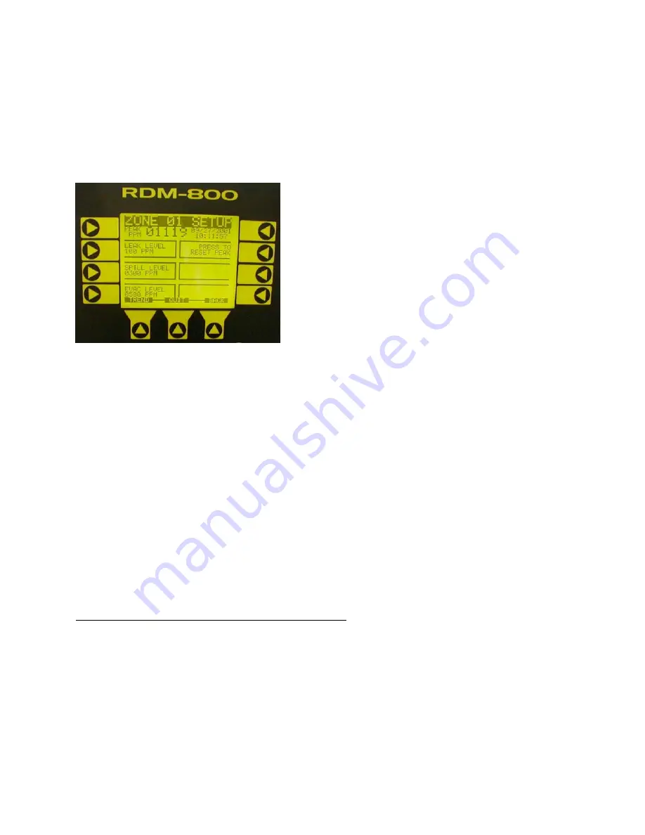
Press
ì LEAK
LEVELî
button.
Use
left/right
keys
to
move
across
and
up/down
keys
to
readjust
leak
alarm
PPM
level
to
desired
PPM
level.
10)
Press
ì SPILL
LEVELî
button.
Repeat
as
in
step
8.
11)
Press
ì EVACUATE
LEVELî
Button.
Repeat
as
in
step
8.
Note:
The
evacuate
level
must
be
greater
than
or
equal
to
the
spill
level,
which
must
be
greater
than
or
equal
to
the
leak
level.
12)
Press
ì RESET
PEAKî
button.
Use
the
to
clear
the
previous
peak
PPM
displayed
for
this
zone.
This
key
is
used
to
clear
the
peak
PPM
for
this
zone,
which
is
displayed
at
the
top
of
this
screen.
The
peak
PPM
gives
the
PPM
level,
time
and
date
of
the
highest
refrigerant
readings
since
the
unit
was
last
cleared
(or
started,
if
the
reading
has
never
been
cleared).
The
peak
PPM
reading
along
with
the
TREND
DATA
can
be
a
powerful
diagnostic
tool
in
detecting
small
leaks
before
they
become
large
leaks.
13)
To
move
to
the
next
zone
set
up
screen
press
the
right
keypad
button.
Use
the
ì BACKî
button
to
move
to
the
first
zone
set
up
screen.
Repeat
steps
2
to
13
to
program
the
second
zone.
Repeat
as
necessary
for
all
zones
in
monitor.
To
return
to
the
SYSTEM
SCREEN,
press
QUIT
then
press
SYSTEM.
PROGRAMMING
USING
THE
HGM300
PC
SOFTWARE
Note
ñ
There
are
two
versions
of
software
and
firmware.
Version
1.0
generally
is
found
in
HGM300
serial
numbers
beginning
with
AJ00
to
serial
numbers
beginning
with
AF01
and
version
1.25
from
serial
numbers
beginning
with
AF01
forward.
If
an
RDM800
is
connected
to
the
unit
the
version
of
the
firmware
can
be
obtained
from
the
HGM300
Main
screen.
Insert
software
disk
into
PC.
Note:
The
PC
software
uses
COM1
by
default.
Therefore,
the
interface
cable
should
be
connected
to
the
port
configured
as
COM1
on
the
PC.
Also,
no
other
software
drivers
or
devices
in
the
PC
may
control
COM1
when
the
HGM300
software
is
in
use.
The
connection
is
made
through
a
standard
ì straight
throughî
serial
port
connection.
A
three-wire
connection
is
used
(RXD,
TXD,
and
GND).
No
hardware
flow
control
is
used.
The
HGM300
software
automatically
configures
COM1
to
match
the
HGM300
RS-232
communications
parameters.
Turn
on
power
to
HGM300.
SETUP
SCREEN
#
2
Archived
Document


