


Rev.
10/22/01
HGM300/RDM800
mini
manual.doc
14
2)
BENCH
TEMP
FAULT
ñ
Optical
bench
is
outside
of
normal
operating
range
(or
sensor
has
failed).
Check
the
installation
to
verify
that
the
monitor
is
not
being
subjected
to
extreme
temperatures.
Check
the
DIAGNOSTIC
SCREEN
for
the
ZERO
temperature,
BNCH
temperature
and
BOX
temperature.
Call
the
factory
with
this
information
at
1-800-888-6400
Ext.
5182,
5169
or
5403
for
farther
instructions.
3)
PRESSURE
SENSOR
ñ
Manifold
pressure
is
outside
normal
operating
range
(or
sensor
has
failed).
Check
the
DIAGNOSTIC
SCREEN
record
ALL
data
and
call
the
factory
with
this
information
at
1-800-888-6400
Ext.
5182,
5169
or
5403
for
farther
instructions.
4)
LOOP
FAULT
ñ
This
would
only
be
displayed
if
the
dual
4-20mAdc
option
was
installed
and
one
or
both
current
loops
are
open.
Check
the
wiring
to
load/monitoring
circuit
on
both
4-20mA
loops.
5)
CONFIG
FAULT
ñ
There
is
an
error
in
the
ZONE
SETUP
SCREEN,
Number
of
zones
field.
Check
to
verify
that
the
actual
number
of
zones
installed
in
the
monitor
is
equal
to
the
number
indicated
in
the
Zone
Setup
Screen.
Check
to
insure
that
the
manifold
solenoid
cable
connector
is
securely
fastened
to
its
terminal
connector.
Check
for
illegal
parameter.
Reset
to
factory
default
settings.
Reset
to
factory
default
settings
-
Hold
down
the
left
most
button
inside
the
HGM300
ñ
cycle
the
power
off
then
on
while
holding
that
button
down
ñ
listen
for
five
beeps
then
release
the
button.
Reprogram
the
HGM300.
Note
ñ
Performing
this
function
wipes
out
all
program
parameters,
alarms,
faults,
trends
and
log
files.
Resetting
the
RDM800
to
factory
default
settings
ñ
Occasionally
it
will
be
necessary
to
rest
the
RDM800
to
factory
default
settings.
From
the
System
Screen,
press
and
hold
the
button
adjacent
to
the
ì ALARMî
function,
cycle
power
off
then
on,
listen
for
five
beeps.
FAULT
LOG
SCREEN
ñ
From
the
FAULT
SCREEN
press
the
button
under
LOG.
This
screen
lists
the
last
20
fault
conditions
recorded
by
the
system.
Using
the
left/right
keys
on
the
keypad
you
can
move
across
the
screen
to
view
the
time
and
date
of
the
fault.
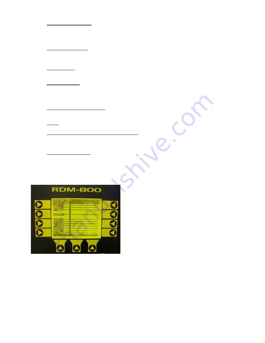
FAULT
LOG
SCREEN
Archived
Document


