


<6. Operation>
6-2
IM 01C27H01-01EN
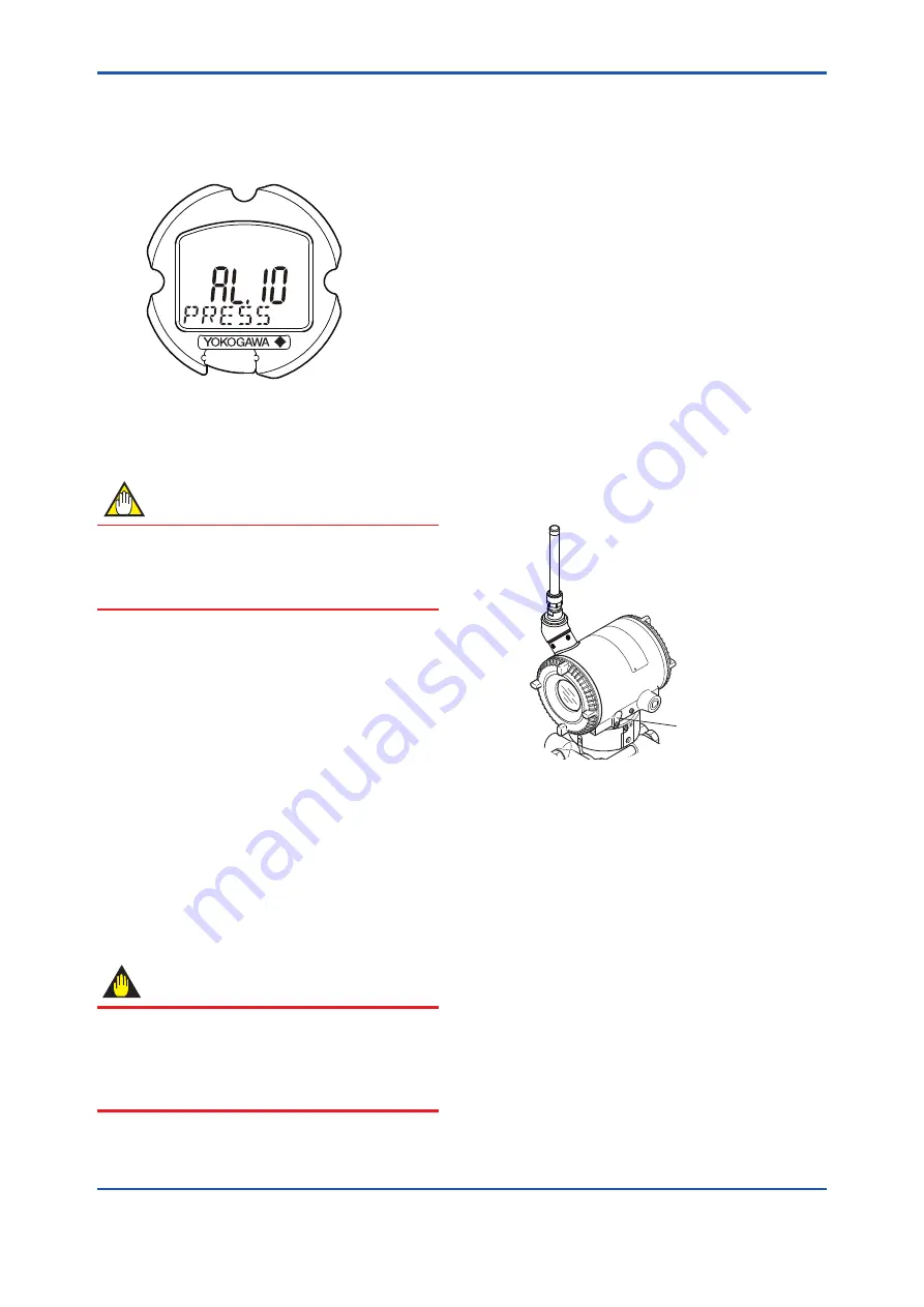
■ Confirm that transmitter is operating
properly by integral indicator.
• If the transmitter is faulty, an error code is
displayed.
F0603.ai
Self-diagnostic error on integral indicator
(Faulity transmitter)
Figure 6.3
Integral Indicator with Error Code
NOTE
If any of the above errors are indicated on the
display of the integral indicator or the device
configuration tool, refer to subsection 8.5.3 for
the corrective action.
■
Verify and Change Transmitter Parameter
Setting and Values
The parameters related to the following items are
minimum required to be set for operation, and set at
factory as specified in order. Confirm or change the
parameters if needed.
• Measurement range(measurement lower/upper
limit, unit)
• Output (Non linearization mode / Sq root mode)
6.2 Zero Point Adjustment
After completing preparations for operating the
transmitter, adjust the zero point. There are two
zero point adjusting ways.
IMPORTANT
Do not turn off the power to the transmitter
immediately after performing a zero point
adjustment. Powering off within 30 seconds of
performing this procedure will return the zero
point to its previous setting.
(1) When you can obtain the Low Range Value
from the actual measured value of 0%
(0 kPa, atmospheric pressure);
■
Using the transmitter’s zero-adjustment
screw
Before adjusting zero point, make sure
followings.
• The External zero trim parameter
(External Zero Trim) is “Trim on”. For details,
refer to section 7 “Setting Parameters”.
• Use a slotted screwdriver to turn the zero
adjustment screw. Turn the screw clockwise
to increase the output or counterclockwise to
decrease the output.
• The zero point adjustment can be made with
a resolution of 0.01% of the setting range.
The degree of zero adjustments varies with
the screw turning speed; turn the screw
slowly to make a fine adjustment, quickly to
make a rough adjustment.
External Zero
Adjustment Screw
F0604.ai
Figure 6.4
External Zero Adjustment Screw


