


INST
ALLER'S
INSTRUCTION
INST
ALLER'S
INSTRUCTION
P31 OF 38
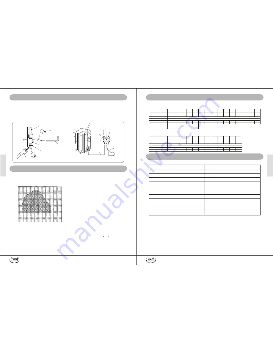
OPERATION FREQUENCY
CONDENSING PRESSURE (MPa (G))
580
4.0
3.5
3.0
2.5
2.0
1.5
0
507
435
362
290
217
0
20
40
60
80
100
120
140
CONDENSING PRESSURE (PSI (G))
SYSTEM INSPECTION AND TRIAL RUNNING
Evacuate the pipes between indoor and outdoor units, using vacuum pump and manifold/gauge set, to a
minimum of 500 microns (service valves remain front seated). Hold for 30 minutes to check if the vacuum level is
maintained. Using dry nitrogen or other leakage detection tool for leak checking. Be certain there is no pressure
in the system when repairing a leak.
VACUUM REFRIGERANT PIPES
VACUUM AND LEAKAGE CHECK
P32 OF 38
CHECK AFTER INSTALLATION AND TEST OPERATION
1) Before test operation
1) Do not turn on power before installation is finished
completely.
2) Electric wires must be connected correctly and
securely.
3) Cut-off valves of the connection pipes should be
back seated/
on.
turned
4) All the left over installation material scraps must be
cleared away from the unit before initial start up.
2) Test operation method
1) Switch on power, press "ON/OFF" button on the
wireless remote control to start the operation.
2) Press MODE button, to select the COOL, HEAT
(not available for cooling only
), FAN and so
on to check :
unit's
* All the functions (to make sure the unit functions
correctly and properly).
* Refrigerant (pressures/temperatures at service
values/pipes should be good).
* Drainage (condensate/water flow should be
dripping out of drainage pipe ONLY).
* Noise (there should be not any abnormal sound).
Has the unit been positioned firmly?
The unit may drop, shake or emit noise.
Have you done the refrigerant leakage test?
It may cause insufficient cooling(heating), or compressor
overheating, or other unit
malfunctions.
Is heat insulation sufficient?
It may cause unexpected condensate and dripping.
Is drainage pipe tested ?
It may cause leakage or
dripping.
unexpected
Is the voltage in accordance with the rated voltage marked on
the nameplate?
It may cause unit malfunction or damage to the part/unit.
Is the electrical wires and pipes connection installed correctly
and securely?
It may cause unit malfunction or damage to the part/unit.
Has the unit been connected to a secure ground connection?
It may cause electric leakage.
Is the power cord specified properly per NEC codes ?
It may cause wire overheat or even fire.
Is the air inlet and outlet been cleared?
It may cause insufficient cooling/heating capacity, and
unexpected noise.
CHECK AFTER INSTALLATION
TEST OPERATION
SYSTEM INSPECTION AND TRIAL RUNNING
Vacuum and Check Leakage before Releasing Refrigerant from Outdoor Unit to Indoor Unit
Service valve
Hexagon
Allen wrench
3-way valve
Blank cap
Refrigerant pipe
Outdoor unit
Cap
Service hose
with valve core
Compound pressure gauge
Gauge manifold
Pressure gauge
High pressure
side valve
(closed)
Service hose
Vacuum pump
Service hose
Low pressure
side valve
-100 kPa
-76cm.Hg
-1 bar
(For a description of how to use the
gauge manifold, refer to the gauge
manifold operation manual.)
Warning:
R410A refrigerant bears higher pressures than R22.
Only handled by Licensed HVAC technician.
Outdoor Dry-Bulb (F)
Outdoor Dry-Bulb (C)
Outdoor Wet-Bulb (F)
Outdoor Wet-Bulb (C)
Indoor Dry-Bulb
Indoor Wet-Bulb
Discharge-PSI/F
Suction-PSI/F
15
-9.4
13.6
-10.2
25
-3.9
23.0
-5
35
1.7
30.2
-1.0
50
10.0
42.8
6.0
55
12.8
46.9
8.3
60
15.6
51.1
10.6
67
19.4
59.5
15.3
75
23.9
66.6
19.2
82
27.8
64.9
18.3
90
32.2
71.2
21.8
95
35.0
75.0
23.9
100
37.8
79.0
26.1
105
40.6
82.9
28.3
110
43.3
86.9
30.5
115
46.1
90.7
32.6
74/21.2
84/27.1 105/35.1 115/38.5 125/42.8 130/45.5 140/48.2 146/51.2 156/54.3 166/57.5 175/61.2 180/62.5 186/63.7 189/64.5 191/64.9
60/46.2
70/53.5
85/55.2
92/55.7
98/56.1 103/56.7 110/56.9 115/57.1 120/57.5 128/57.8 135/57.9 136/58.6 137/59.1 139/59.3 140/59.5
80F (26.7C)
67F (19.4C)
Suggest to Add on Low Ambient Control, If Still
in Need of AC for Long Time In Cold Weather.
Closely Check/Watch Refrigerant Charge Level.
Reference Temperature-Pressure Table (Split Condensing Unit-R410A AC)
Product Series: YMGI Group-Mini Split Version: 01/11/2010
Reference Temperature-Pressure Table (Split Condensing Unit, R410A-Heat Pump)
Product Series: YMGI Group-Mini Split System Version: 01/11/2010
Outdoor Dry-Bulb (F)
Outdoor Dry-Bulb (C)
Outdoor Wet-Bulb (F)
Outdoor Wet-Bulb (C)
Indoor Dry-Bulb
Indoor Wet-Bulb
Discharge-PSI/F
Suction-PSI/F
0
-17.8
-0.8
-18.2
5
-15
4.1
-15.5
10
-12.2
8.8
-12.9
17
-8.3
15
-9.4
25
-3.9
22.8
-5.1
30
-1.1
27.5
-2.5
35
1.7
28.9
-1.7
40
4.4
36.3
2.4
45
7.2
41.0
5
47
8.3
43.0
6.1
55
12.8
50.4
10.2
62
16.7
56.5
13.6
70F (21.1C)
60F (15.6C)
260/84
269/90
284.5/95
290/102
296/111
304/128
304/133
330/138
345/142
354/149
400/149
440/176
246/72
255/78
270/86
278/89
285/92
290/95
310/98
318/100
330/102
340/104
380/107
425/113
PRESSURE CHECKING
CHECK SYSTEM THOROUGHLY
Check system thoroughly to make sure the unit is ready for trial running:
check wires and pipes and air intake and discharge and power and
thermostat and others necessary components.
ADJUST REFRIGERANT-
GUIDELINE
Right amount of refrigerant is very important. It is one of the
basics to ensure a safe operation over time.
Normally single zone outdoor unit is pre-charged with
refrigerant for 25ft inter-connecting copper (liquid) line.
Multiple zone outdoor unit is pre-charged for various length
of copper (liquid) lines of allowed quantity of indoor units,
following specs. or engineering submittal.
For single zone unit or multiple zone multiple compressor unit,
normally the outdoor unit is pre-charged for 25ft line sets. If
the copper line is longer or shorter than 25ft, need to add or
deduct refrigerant, following general rule of thumb for rough
adjustment: 1/4" liquid line unit: 0.3 Oz/ft;
3/8" liquid line unit: 0.4 OZ/ft; 1/2" liquid line unit: 1.2 OZ/ft.
For multiple zone one compressor unit, if the copper line is
longer or shorter than the length at which pre-charged
refrigerant is good for, as listed in the engineering submittal
or related labels or tables, need to add or deduct refrigerant,
following 0.23 OZ/ft rule of thumb for rough adjustment.
In all situations, the minimum copper line (liquid or gas)
length for each indoor unit is 15ft.
For a better adjustment, may combine above guideline with
the indoor or outdoor (ambient) temperature-refrigerant
pressure chart, or generally 8-12F super-heat method.
System pressure checking should be a must-do job during trial running of initial installation, and compressor/refrigerant-related trouble-
shooting. It is a more accurate refrigerant adjusting method than rough refrigerant addition or deduction guideline shown above.
In some cases, if the service valve on unit is 5/16
and your service valve connection is 1/4
, need to use a 5/16
-1/4
adaptor so that
you can connect to your manifold. Need to pay attention to use the right manifold that is rated for the refrigerant in the unit, and pay attention
to connect to the right hose (blue hose for low pressure, red hose for high pressure, yellow hose for vacuum or charging or deduction). Not
to put hose onto service valve while compressor is running. Remove hose quickly and carefully to avoid air suck-in, refrigerant
leakage, or any refrigerant-freezing burn.
recommended
The following curves are only reference for system pressure checking. Actual pressures may vary upon many factors such as inter-connecting
pipe length, refrigerant charge / leakage level, elevation difference between indoor unit and outdoor unit, tool calibration, reading error, and so
on.
Items to be checked
Has the refrigerant pressure been checked or refrigerant
been adjusted accordingly?
It may generate unexpected noise, freezing pipe, capacity
issues, compressor or system damage or even worse.
Has the installing technician filled all the fields in the
checklist inside the warranty registration card?
If not filed or not filled completely or correctly, your factory
warranty may not be qualified.
Possible Problems or Consequences
YMGI, Engineered Comfort Products for A Sustainable and Efficient Green World !
YMGI, Engineered Comfort Products for A Sustainable and Efficient Green World !


